Drift calibration method and device for the potentiometric sensor

Inactive Publication Date: 2007-04-19
CHUNG YUAN CHRISTIAN UNIVERSITY
View PDF4 Cites 10 Cited by
  • Summary
  • Abstract
  • Description
  • Claims
  • Application Information

AI Technical Summary

Benefits of technology

[0016] Another purpose of this invention is to provide one auto-assembling system to combine the control circuit to control the transportation and assemble the frames and covers to assemble the small shell devices; it can also collect the frames and covers

Problems solved by technology

Due to wet storage, fragility, big size and high cost, the solid-state electrodes have been developed to substitute for the glass electrode.
The drift, which is t

Method used


Image

  • Drift calibration method and device for the potentiometric sensor
  • Drift calibration method and device for the potentiometric sensor
  • Drift calibration method and device for the potentiometric sensor

Examples


Embodiment Construction

[0032] Some sample embodiments of the invention will now be described in greater detail. Nevertheless, it should be recognized that the present invention can be practiced in a wide range of other embodiments besides those explicitly described, and the scope of the present invention is expressly not limited expect as specified in the accompanying claims. Then, the components of the different elements are not shown to scale. Some dimensions of the related components are exaggerated and meaningless portions are not drawn to provide clearer description and comprehension of the present invention.

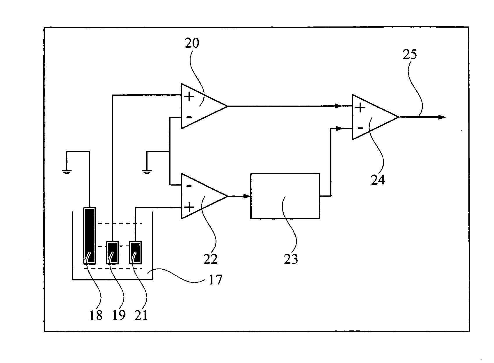
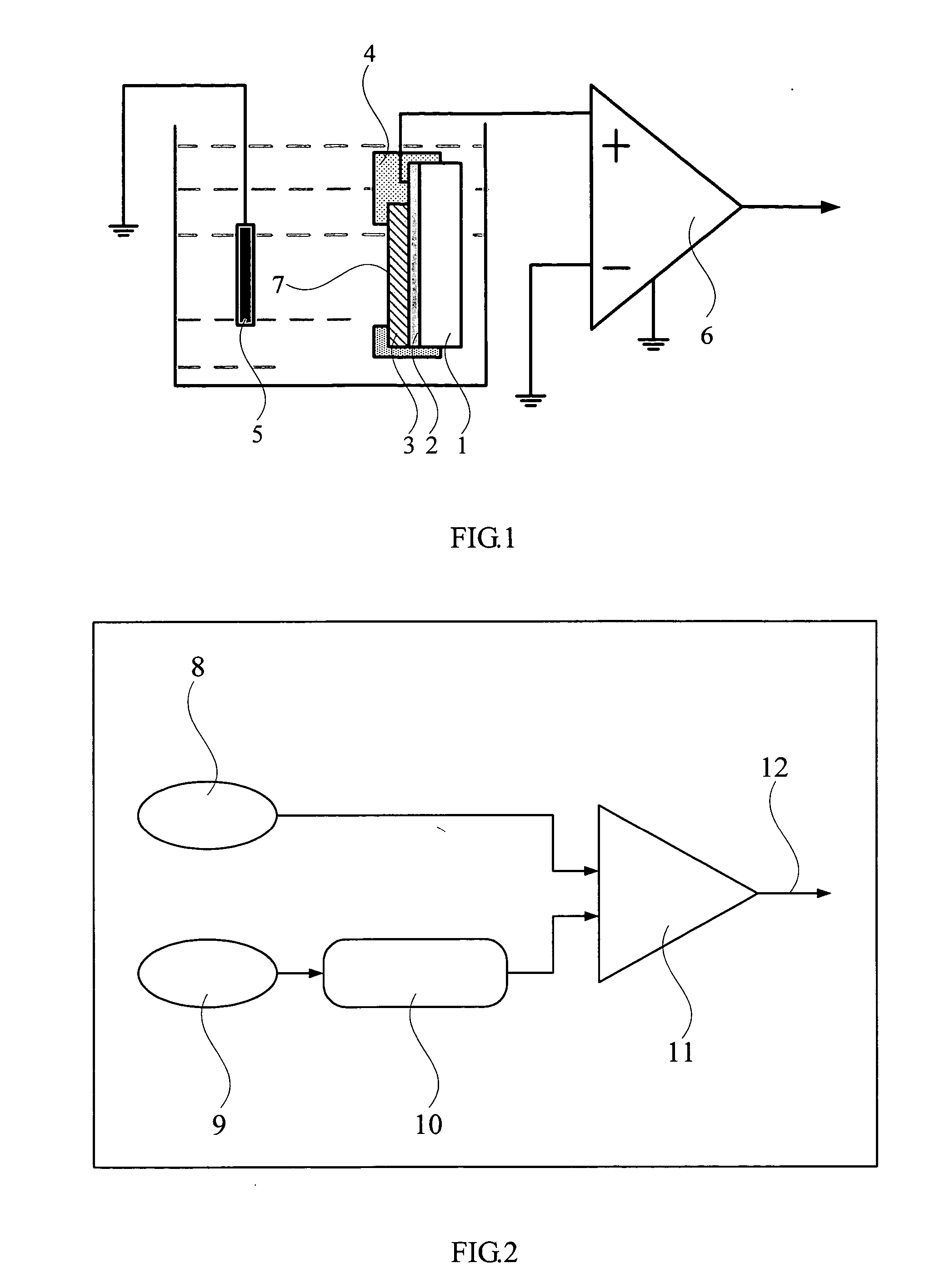
[0033] Referring to FIG. 1, showing a readout circuit of the potentiometric sensor, wherein the sensing element 30 connects to positive input end of an instrumentation amplifier 6, and the sensing element 30 is used to transform the pH value of a measuring solution 31 to a parameter such as voltage and transfer to positive input end of the instrumentation amplifier 6. A reference electrode 5 wit...


PUM


Abstract

The present invention discloses a method and an apparatus of the drift calibration of sensors. The method includes shifting the sensing signal and differential technology to remove the drift signal by time during a long measuring. The apparatus includes two voltage sensors and readout circuits, a signal-shifting circuit and a differential circuit, and the apparatus is used for outputting the response signal without time drifting.

Description

BACKGROUND OF THE INVENTION [0001] 1. Field of the Invention [0002] The present invention relates to a method of calibrating sensor, and more particularly to calibrate the drift signal that is outputted from the potentiometric sensors during a long-time measuring. [0003] 2. Description of the Prior Art [0004] The direct measurement of the hydrogen ion activity (pH) of the aqueous solution, by means of the glass membrane electrode, has been a valuable technology in analytical chemistry and process monitoring for many years. Due to wet storage, fragility, big size and high cost, the solid-state electrodes have been developed to substitute for the glass electrode. [0005] In 1970, the first ion-sensitive field-effect transistor (ISFET) was fabricated by Bergveld (please refer to reference [1]: P. Bergveld, entitled “Development of an ion-sensitive solid state device for neurophysiological measurements”, IEEE Transactions on Bio-medical Engineering, vol. BME-17, pp. 70-71, 1970.). There ...

Claims


Application Information

Patent Timeline
IPC IPC(8): G01N27/26
CPCG01N27/4165
Inventor HSUNG, SHEN-KANCHOU, JUNG-CHUANSUN, TAI-PINGPAN, CHUNG-WETSAI, CHU-NENG
Owner CHUNG YUAN CHRISTIAN UNIVERSITY
Why Eureka
Try Eureka