Semiconductor integrated circuit device

a technology of integrated circuits and semiconductors, applied in the direction of oscillator generators, angle modulation by variable impedence, electrical equipment, etc., can solve the problems of not being able to follow oscillation frequency variations, vco might not be able to operate stably, and not fulfilling the function of voltage controllable oscillator circuits

Inactive Publication Date: 2007-04-19
NEC ELECTRONICS CORP
View PDF6 Cites 26 Cited by
  • Summary
  • Abstract
  • Description
  • Claims
  • Application Information

AI Technical Summary

Problems solved by technology

However, since the capacitance of the variable capacitance circuits is controlled to vary over a wide range of the control voltage in the LC-VCO disclosed in Patent Document 1, it is difficult for it to operate stably if the range in which the control voltage varies is narrow.
On the other hand, in case where when it is simply controlled so that the capacitance of a single variable capacitance circuit varies in order to deal with the narrow range in which the control voltage varies, the VCO might not be able to follow variations in oscillation frequency caused by the fluctuations of the temperature and the power supply voltage, and it might not fulfill the function as a voltage controllable oscillator circuit.
In other words, the circuit characteristics of the oscillator circuit are changed by temperature fluctuations and power supply voltage fluctuations, and over a narrow range of the control voltage, it is difficult to control the capacitance so that the circuit oscillates at a predetermined oscillation frequency.

Method used


Image

  • Semiconductor integrated circuit device
  • Semiconductor integrated circuit device
  • Semiconductor integrated circuit device

Examples


embodiment 1

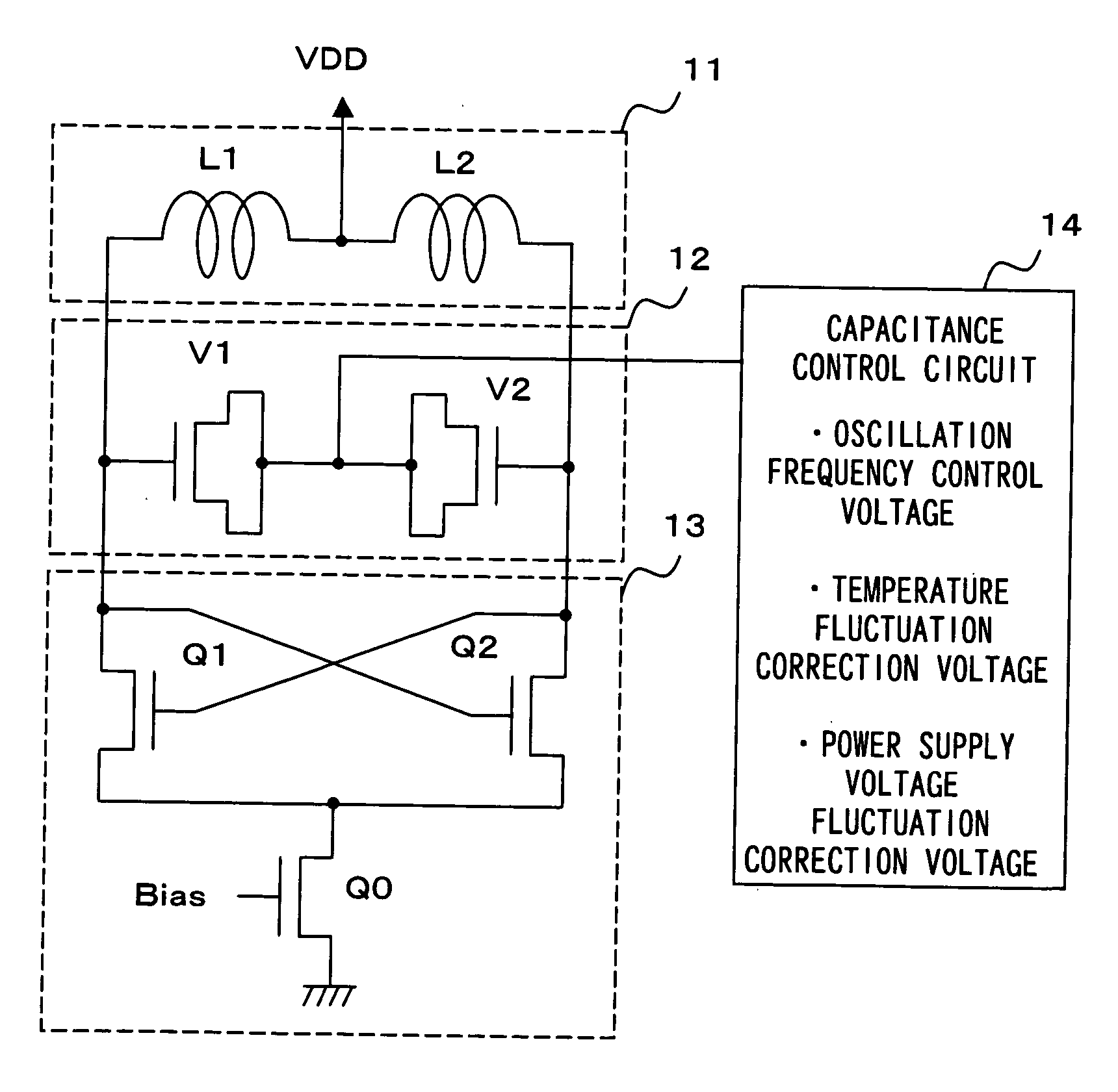
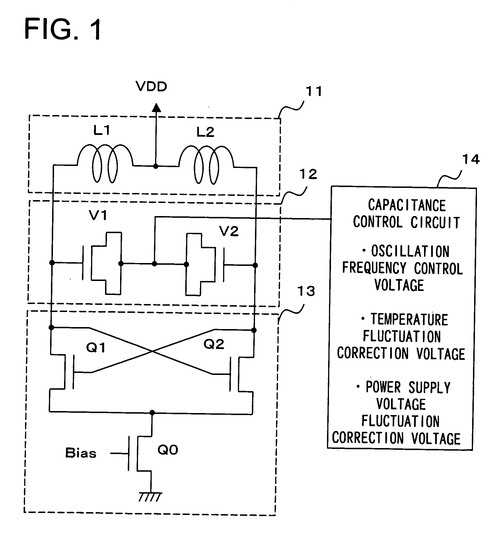
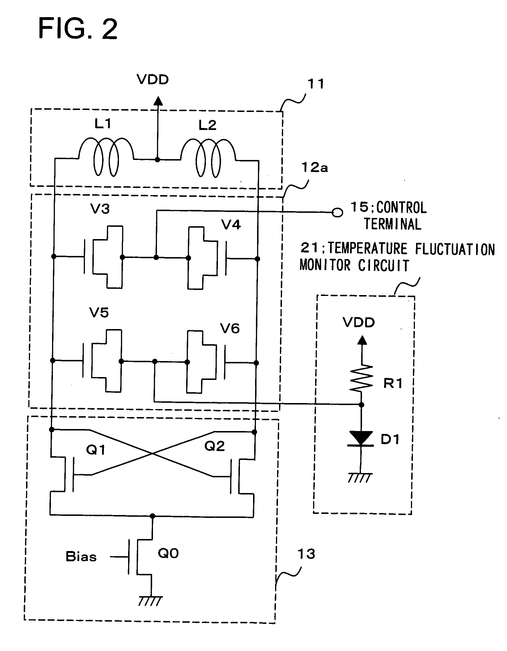
[0035] In a first embodiment, an example where the capacitance of the variable capacitance circuit is controlled by a correction voltage outputted in response to temperature fluctuations is described. FIG. 2 is a circuit diagram illustrating the structure of a voltage-controlled oscillator relating to the first embodiment of the present invention. In FIG. 2, the same symbols as the ones in FIG. 1 represent the same things, thus explanations of them will be omitted. A variable capacitance circuit 12a is constituted by cascade-connected variable capacitance elements V3 and V4 and variable capacitance elements V5 and V6, also cascade-connected. The variable capacitance elements V3 and V4 share a common end (node), which is connected to a control terminal 15. The variable capacitance elements V5 and V6 share a common end (node), which is connected to the anode of a diode D1 in a temperature fluctuation monitor circuit 21. The other ends of the variable capacitance elements V3 and V5 are...

embodiment 2

[0039] In a second embodiment, another example where the capacitance of the variable capacitance circuit is controlled by a correction voltage outputted in response to temperature fluctuations is described. FIG. 3 is a circuit diagram illustrating the structure of a voltage-controlled oscillator relating to the second embodiment of the present invention. In FIG. 3, the same symbols as the ones in FIG. 2 represent the same things, thus explanations of them will be omitted. The variable capacitance elements V5 and V6 share a common end (node), which is connected to one end of a resistance element R3 in a temperature fluctuation monitor circuit 21a.

[0040] The temperature fluctuation monitor circuit 21a comprises a resistance element R2 having one end connected to the power supply VDD and the other end connected to one end of the resistance element R3, and the resistance element R3 having one end connected to the other end of the resistance element R2 and the other end grounded. Furthe...

embodiment 3

[0042] In a third embodiment, an example where the capacitance of the variable capacitance circuit is controlled by a correction voltage outputted particularly in response to power supply voltage fluctuations is described. FIG. 4 is a circuit diagram illustrating the structure of a voltage-controlled oscillator relating to the third embodiment of the present invention. In FIG. 4, the same symbols as the ones in FIG. 2 represent the same things, thus explanations of them will be omitted. A variable capacitance circuit 12b is constituted by the cascade-connected variable capacitance elements V3 and V4 and variable capacitance elements V7 and V8, also cascade-connected. The variable capacitance elements V7 and V8 share a common end (node), which is connected to the drain of an NchMOS transistor Q4 in a voltage fluctuation monitor circuit 22. The other ends of the variable capacitance elements V3 and V7 are connected in common to the other end of the inductor L1. The other ends of the v...


PUM


Abstract

A voltage-controlled oscillator operates stably over a narrow variation range of a control voltage, including a variable capacitance circuit 12 controllable by voltage, an inductor circuit 11 having inductors, a negative resistance circuit 13, and a capacitance control circuit 14 that outputs a correction voltage. An oscillator circuit is constituted by the variable capacitance circuit 12, the inductor circuit 11, and the negative resistance circuit 13 connected in parallel. The capacitance control circuit 14 controls to correct the capacitance of the variable capacitance circuit 12 with the correction voltage outputted in response to a temperature fluctuation and / or power supply voltage fluctuation in the oscillator circuit.

Description

FIELD OF THE INVENTION [0001] The present invention relates to a semiconductor integrated circuit device, and particularly to a semiconductor integrated circuit device including a voltage controllable oscillator circuit. BACKGROUND OF THE INVENTION [0002] As a local oscillator in a phase locked loop (PLL) circuit used for the purposes of frequency multiplication or phase synchronization, a ring oscillator was conventionally used. A ring oscillator is constituted by an odd-number of CMOS (Complementary Metal Oxide Semiconductor) inverters connected in a ring, and it can be formed in a MOS integrated circuit. Such a ring oscillator has high jitter in an oscillation signal since it includes many active elements. [0003] Meanwhile, a voltage-controlled oscillator utilizing the resonance of a parallel LC tank circuit (abbreviated as LC-VCO) has been used as a local oscillator in recent years. Compared with the ring oscillator, the LC-VCO has the following advantages. First, the LC-VCO pro...

Claims


Application Information

Patent Timeline
Patent Type & Authority Applications(United States)
IPC IPC(8): H03B5/12
CPCH03B5/04H03B5/1228H03B5/1215H03B5/1265H03B5/1253H03L1/023
Inventor OHKUBO, HIROAKINAKASHIBA, YASUTAKA
Owner NEC ELECTRONICS CORP
Why Eureka
Try Eureka