
Lithographic projection apparatus, device manufacturing method and device manufactured thereby

a technology of lithographic projection and manufacturing method, which is applied in the direction of optical devices, photomechanical devices, instruments, etc., can solve the problems of increasing the industry toward even shorter-wavelength radiation and considerable problems, and achieve the effect of reducing the operational performan

Inactive Publication Date: 2007-04-19
ASML NETHERLANDS BV
View PDF32 Cites 4 Cited by
  • Summary
  • Abstract
  • Description
  • Claims
  • Application Information

AI Technical Summary

Benefits of technology

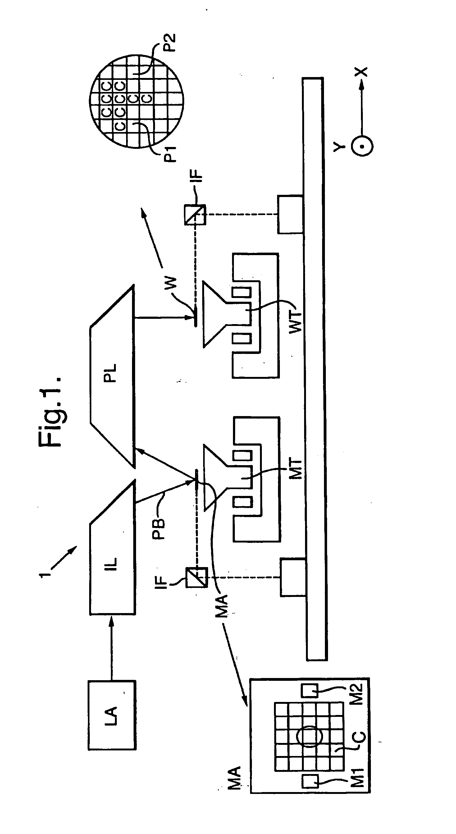
[0008] It is an aspect of the present invention to provide lithographic projection apparatus including a radiation system configured to supply a beam of radiation; a mask table configured to hold a mask; a substrate table configured to hold a substrate; a projection system configured to image an irradiated portion of the mask onto a target portion of the substrate, which apparatus is compatible for use in a vacuum or semi-vacuum environment. In particular, it is an aspect of the present invention that such an apparatus should be compatible with the use of radiation including EUV, charged particles or X-rays. More specifically, it is an aspect of the invention that such an apparatus should not suffer from significant “down-time” due to decrease of operational performance caused by degeneration of the projection system.
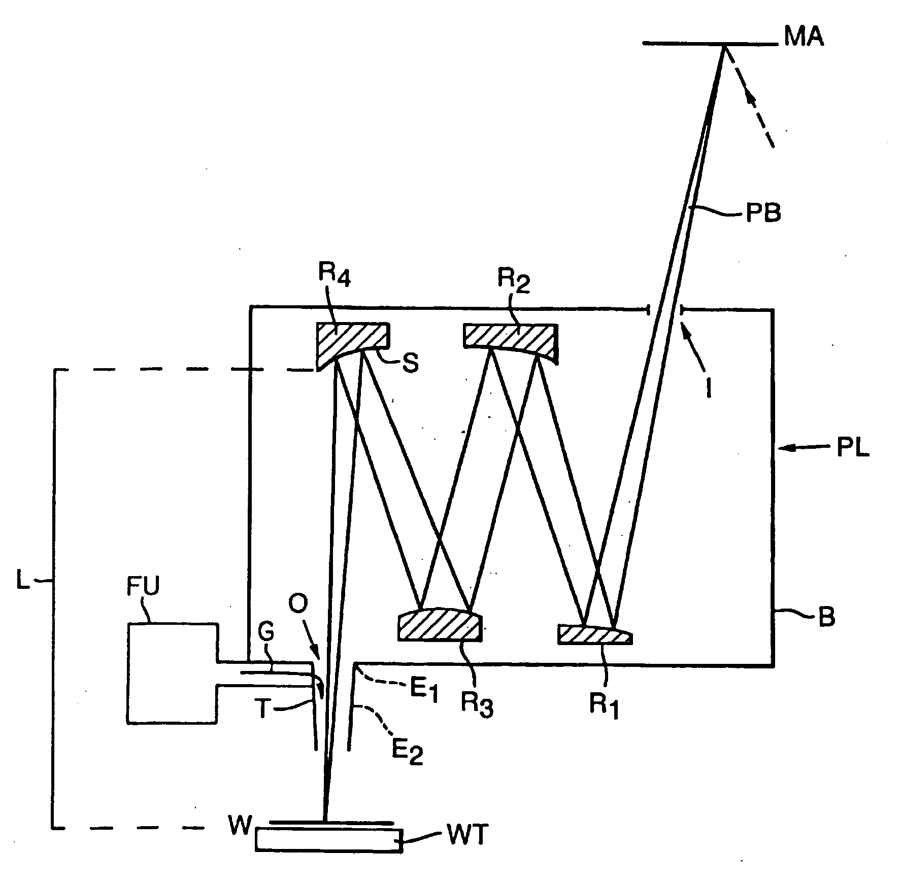
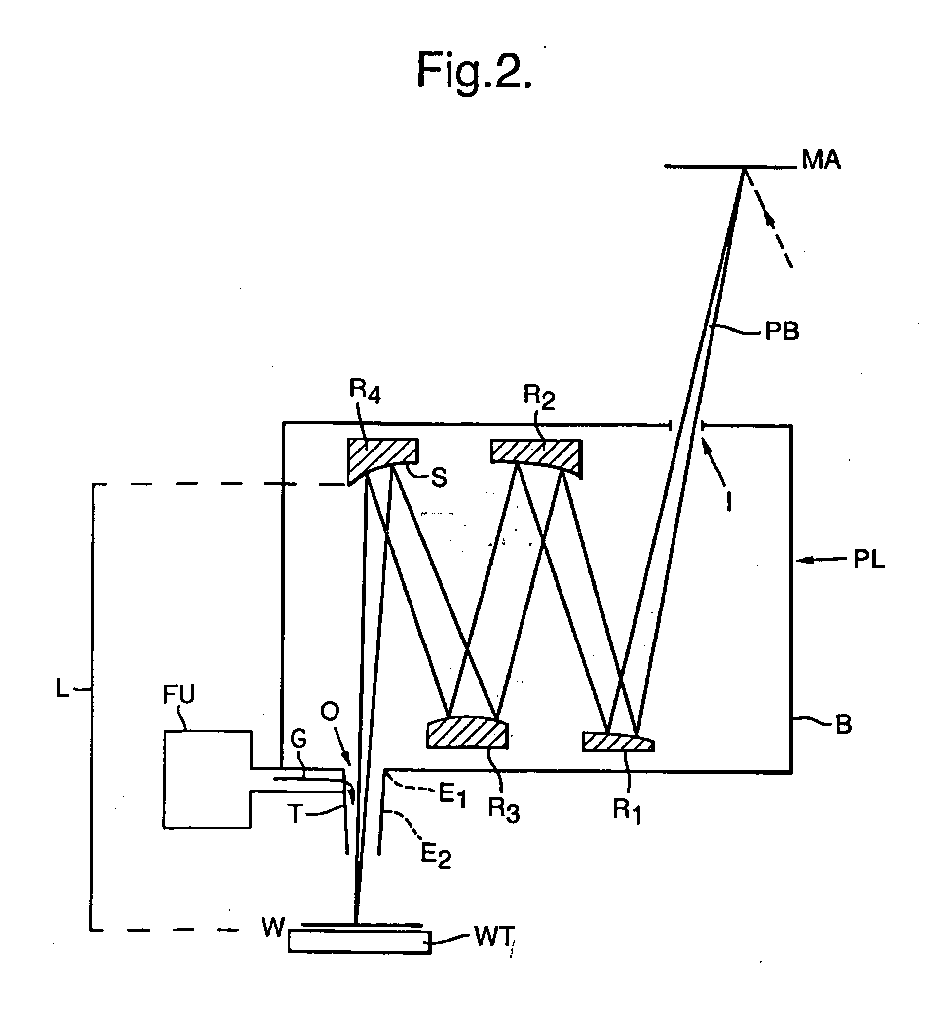
[0012] In experiments leading to the present invention, the inventors built a prototype device in which the radiation system delivered EUV (with a wavelength of approx. 13.4 nm). A projection system (including various mirrors) was used to focus the laser radiation onto a substrate table, onto which a test wafer could be mounted. A substantially evacuated enclosure, delimited (bounded) at one end by the exit aperture of the laser and at the other end by the substrate table, was provided around the projection system, so that the path of the radiation from source to substrate was substantially airless, including therefore the intervening space between the projection system and the substrate table. This intervening space was delimited on the side facing the substrate table by the last mirror in the projection system (the “solid surface” referred to hereabove). Such evacuation was done because of the fact that EUV undergoes significant absorption in air, and was aimed at avoiding substantial light-loss at substrate level.
[0014] In an effort to combat this problem, the inventors increased the distance between the substrate table and the projection system, but rapid contamination of the final optical surface of the projection system was still observed. Subsequent calculations revealed that such an approach was unsatisfactory, and that a more radical anti-contamination measure was required. Eventually, after trying various other approaches, the inventors arrived at the solution described above. In the inventive solution, the flush of gas prevents resist debris from reaching the projection system in the first place.
[0017] A dynamic gas lock which describes a flow going in the same direction as the projected radiation, which further has a membrane or window through which the projected radiation must be transmitted is described in U.S. Pat. No. 6,683,936, U.S. Pat. No. 6,642,996 and U.S. Pat. No. 5,305,364. The hollow tube of these latter documents that directs the inert gas may be cone-shaped and is covered at its top end by a membrane through which the radiation must travel before impinging on the substrate. The membrane prevents the inert gas from flowing upwards towards the projection system.
[0019] The present invention seeks to prevent the loss of EUV radiation, while providing the effects of a dynamic gas lock.
[0020] The apparatus of the present invention includes a hollow tube having the form of a cone, which tapers inwards in a direction extending from the solid surface towards the substrate table. As the projection system serves to focus an image onto the substrate, the radiation emerging from the projection system will taper inwards toward the final image on the wafer. If the employed hollow tube is of a conical form that imitates this tapering, then the tube will have the minimal volume necessary to encapsulate the emergent radiation. This minimizes the flow of gas required to produce an effective flush, leading to materials savings; in addition, the gas load to the system is reduced.

Problems solved by technology

However, the rapidly developing electronics industry continually demands lithographic devices which can achieve ever-higher resolutions, and this is forcing the industry toward even shorter-wavelength radiation, particularly UV light with a wavelength of 193 nm or 157 nm.
This introduces considerable problems.

Method used


Image

  • Lithographic projection apparatus, device manufacturing method and device manufactured thereby
  • Lithographic projection apparatus, device manufacturing method and device manufactured thereby
  • Lithographic projection apparatus, device manufacturing method and device manufactured thereby

Examples


Embodiment Construction

[0037] Resist contamination as hereabove described can be divided in two parts: solvents and exposure products. The solvents are necessary for spinning the resist onto the wafer, but after baking for a few hours at temperatures of the order of 160-175° C., for example, they will generally have evaporated. It is not very likely that complete molecules of the resist will evaporate during exposure, because the molecular mass is too high. However, it is possible that parts of the resist molecules evaporate after they have been cracked by the beam during exposure.

[0038] When resist is illuminated by energetic radiation, the long chains of resist molecules can interconnect or break depending on the type of resist used: negative or positive resist. In the case of breaking, short chains of organic material will be created, and these may evaporate from the resist. In a vacuum system, these particles can travel through the system freely and reach those optical elements of the projection syst...


PUM


Abstract

A lithographic projection apparatus includes a radiation system configured to supply a beam of radiation; a mask table provided with a mask holder for holding a mask; a substrate table provided with a substrate holder for holding a substrate; a projection system configured to image an irradiated portion of the mask onto a target portion of the substrate, wherein the projection system is separated from the substrate table by an intervening space that is at least partially evacuated and is delimited at the location of the projection system by a solid surface from which the employed radiation is directed toward the substrate table; the intervening space contains a hollow tube located between the solid surface and the substrate table and situated around the path of the beam of radiation, the tube being configured such that beam of radiation focused by the projection system onto the substrate table does not intercept a wall of the hollow tube; a flushing system is configure to continually flush the inside of the hollow tube with a flow of gas, wherein the gas is hydrogen, the flow of the gas is opposed to the flow of contaminants from the substrate and / or the hollow tube is in fluid communication with the intervening space.

Description

BACKGROUND OF THE INVENTION [0001] 1. Field of the Invention [0002] The present invention relates to a lithographic projection apparatus, a device manufacturing method and a device manufacture thereby. [0003] 2. Description of the Related Art [0004] A lithographic projection apparatus can be used, for example, in the manufacture of integrated circuits (ICs). In such a case, the mask (reticle) may contain a circuit pattern corresponding to an individual layer of the IC, and this pattern can then be imaged onto a target area (die) on a substrate (silicon wafer), which has been coated with a layer of photosensitive material (resist). In general, a single wafer will contain a whole network of adjacent dies, which are successively irradiated through the reticle, one at a time. In one type of lithographic projection apparatus, each die is irradiated by exposing the entire reticle pattern onto the die at once; such an apparatus is commonly referred to as a waferstepper. In an alternative a...

Claims


Application Information

Patent Timeline
IPC IPC(8): G03B27/52
CPCG03F7/70841G03F7/70908G03F7/70933
Inventor BANINE, VADIM YEVGENYEVICHIVANOV, VLADIMIR VITALEVITCHMERTENS, BASTIAAN MATTHIASMOORS, JOHANNES HUBERTUS JOSEPHINAWOLSCHRIJN, BASTIAAN THEODOOR
Owner ASML NETHERLANDS BV
Learn More