Electrospun Skin Capable Of Controlling Drug Release Rates And Method

a technology of electronic skin and drug release rate, which is applied in the direction of prosthesis, blood vessels, weaving, etc., can solve the problems of difficult dip coating of very small stents, open gap between wires, and dangerous situations, so as to improve conductivity, reduce manufacturing costs, and improve the effect of conducting performan

Inactive Publication Date: 2007-04-19
GREENHALGH SKOTT E +1
View PDF20 Cites 56 Cited by
  • Summary
  • Abstract
  • Description
  • Claims
  • Application Information

AI Technical Summary

Benefits of technology

[0009] The present invention provides an electrospinning process that is useable to create a desired fabric with regularity. By manipulating appropriate variables, the electrospun fibers achieve characteristics that allow them to form a fabric that can adhere to an object, such as a stent, so that the object becomes covered; or the fibers can be used to create a free-standing fabric sheet or “skin” that has a variety of applications. FIG. 5 is a photograph of a stent covered with an electrospun fabric. Further, the skin may be stretched, orienting the fibrils of the skin into planes. Aligning the fibers results in increased tensile strength, altered permeability, reduced bulk, and reduced final part elongation (increased slope on the stress strain curve for the material). These stretching characteristics become very important when using the electrospun material to cover a stent. When the covered stent is deployed and expanded, the membrane cover is stretched radially, which in turn increases the membranes circumferential strength. The electrospun material comprises a plurality of randomly-oriented, inter-tangled, non-woven fibrils having an average diameter of less than 100 micrometers.

Problems solved by technology

Thus, coated stents are made up of a plurality of woven wires that are each coated with a polymer, however, the gaps between the wires remain open.
This is problematic for numerous reasons.
It is difficult to dip coat very small stents because the gaps between the individual wires become clogged with polymer due to the surface tension of the polymer solution.
When the stent later expands, the dried polymer coating cracks and flakes, causing a potentially dangerous situation whereby flakes of polymer enter the blood stream.

Method used


Image

  • Electrospun Skin Capable Of Controlling Drug Release Rates And Method
  • Electrospun Skin Capable Of Controlling Drug Release Rates And Method
  • Electrospun Skin Capable Of Controlling Drug Release Rates And Method

Examples


Embodiment Construction

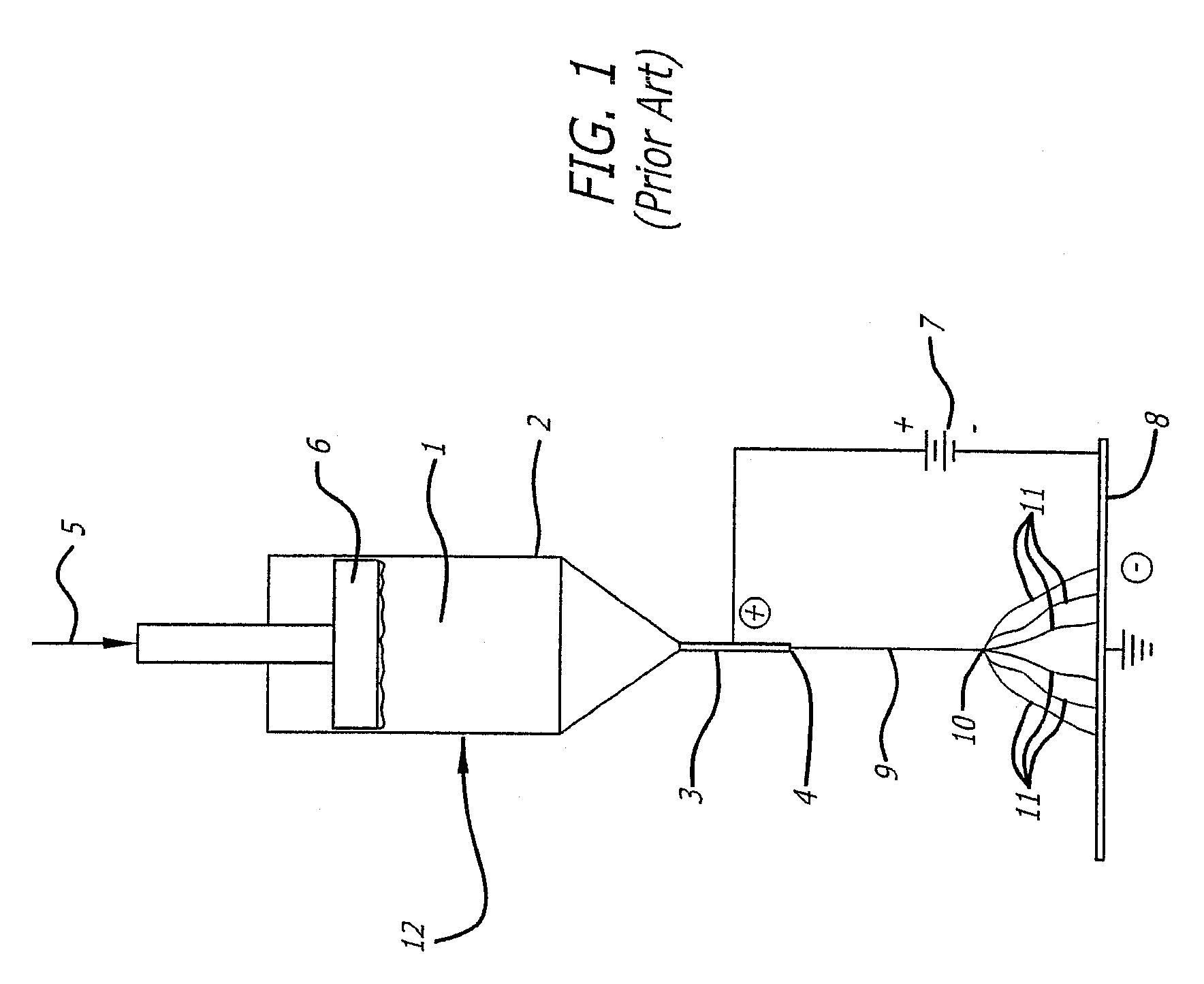
[0043] Mechanical Setup of the Electrospinning Process of the Present Invention

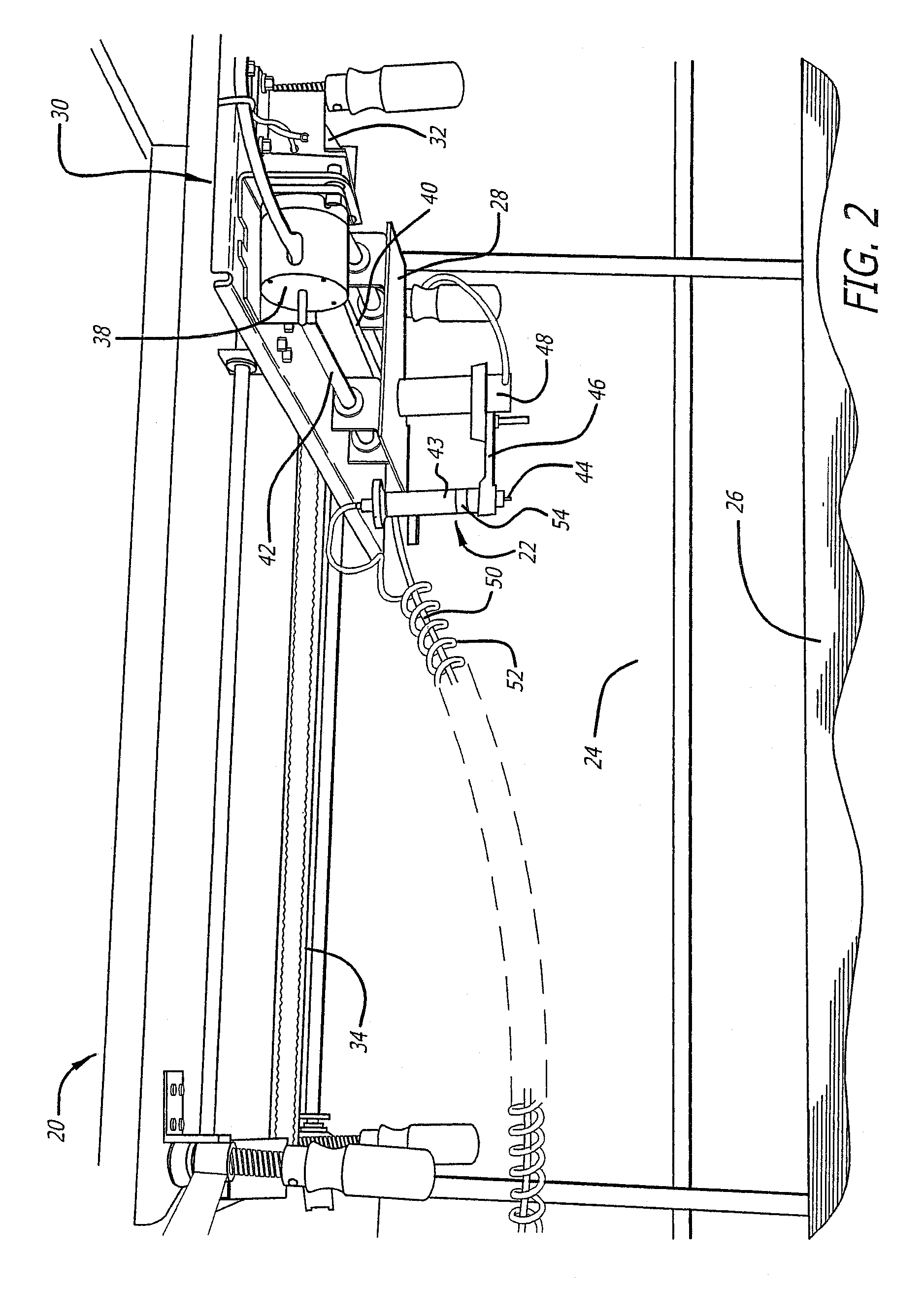
[0044] Referring now to FIG. 2, there is shown a preferred mechanical setup of the electrospinning process of the present invention. Though some of the components are similar to those of FIG. 1, all components have been given new numbers for purposes of clarity.

[0045] The electrospinning apparatus 20 includes a spinneret 22 over a spinning chamber 24, which is defined at its lower end by a collection plate 26. The spinneret 22 is mounted to the carriage 28 of an x-y translator 30, which is preferably an electronically controlled motion system. The x-y translator 30 relocates the spinneret 22 anywhere within the spinning chamber 24 in a horizontal plane at the top of the chamber.

[0046] The x-y translator 30 includes an x motor 32 that is operably attached to a first belt 34 for translating the carriage 28 along a pair of first horizontal guide bars 36. The translator 30 also includes a y motor 38 that i...


PUM

PropertyMeasurementUnit
diametersaaaaaaaaaa
diameteraaaaaaaaaa
diameteraaaaaaaaaa

Abstract

A versatile covering process enabled through the identification and manipulation of a plurality of variables present in the electrospinning method of the present invention. By manipulating and controlling various identified variables, it is possible to use electrospinning to predictably produce thin materials having desirable characteristics. The fibers created by the electrospinning process have diameters averaging less than 100 micrometers. Proper manipulation of the identified variables ensures that these fibers are still wet upon contacting a target surface, thereby adhering with each other to form a cloth-like material and, if desired, adhering to the target surface to form a covering thereon. The extremely small size of these fibers, and the resulting interstices therebetween, provides an effective vehicle for drug and radiation delivery, and forms an effective membrane for use in fuel cells.

Description

CROSS REFERENCE TO RELATED APPLICATIONS [0001] This application is related to U.S. provisional application Ser. No. 60 / 372,721 filed Apr. 11, 2002 and claims priority therefrom.BACKGROUND OF THE INVENTION [0002] The process of the present invention yields a fabric and / or a fabric-like covering having multiple uses, and is particularly suited to medical device and industrial filtration applications. The covering may be created to have a wide range of desired characteristics, depending upon the intended application. The process generally involves electrospinning techniques. [0003] Electrostatic spinning, or “electrospinning” is a process for creating fine polymer fibers using an electrically charged solution that is driven from a source to a target with an electrical field. Using an electric field to draw the positively charged solution results in a jet of solution from the orifice of the source container to the grounded target. The jet forms a cone shape, called a Taylor cone, as it ...

Claims


Application Information

Patent Timeline
Patent Type & Authority Applications(United States)
IPC IPC(8): B32B27/04B32B5/02A61K9/70A61F2/06A61L31/16D01D5/00
CPCA61F2/07A61F2002/072A61L31/16D01D5/0038D01D5/0084D01F1/10A61F2/90Y10T442/696Y10T442/614Y10T442/159Y10T442/2525Y10T442/3472Y10T442/3065
Inventor GREENHALGH, SKOTT E.KIEFER, ROB
Owner GREENHALGH SKOTT E
Why Eureka
Try Eureka