Vehicle gyro based steering assembly angle and angular rate sensor

a technology of angular rate and steering assembly, which is applied in the direction of steering initiation, navigation instruments, instruments, etc., can solve the problems of not using prior art rate gyros for precise estimation of relative angular coordinates between at least two, and achieve the effects of improving sensor robustness and reliability, reducing installation time and cost, and being convenient to us

Active Publication Date: 2007-04-19
TRIMBLE NAVIGATION LTD
View PDF9 Cites 73 Cited by
  • Summary
  • Abstract
  • Description
  • Claims
  • Application Information

AI Technical Summary

Benefits of technology

[0009] The object of the present invention is to provide a robust, inexpensive and easy way to install steering assembly angle sensor to satisfy the Automatic Guidance System continuous feedback, closed loop control steering angle requirement for front wheel steered and articulated steered (center pivot) vehicles. The current technology utilizes rotary and linear style potentiometers (with associate...

Problems solved by technology

However, the prior art rate gyros were not used for precise estimation of relative angular coordinate...

Method used


Image

  • Vehicle gyro based steering assembly angle and angular rate sensor
  • Vehicle gyro based steering assembly angle and angular rate sensor
  • Vehicle gyro based steering assembly angle and angular rate sensor

Examples


example i

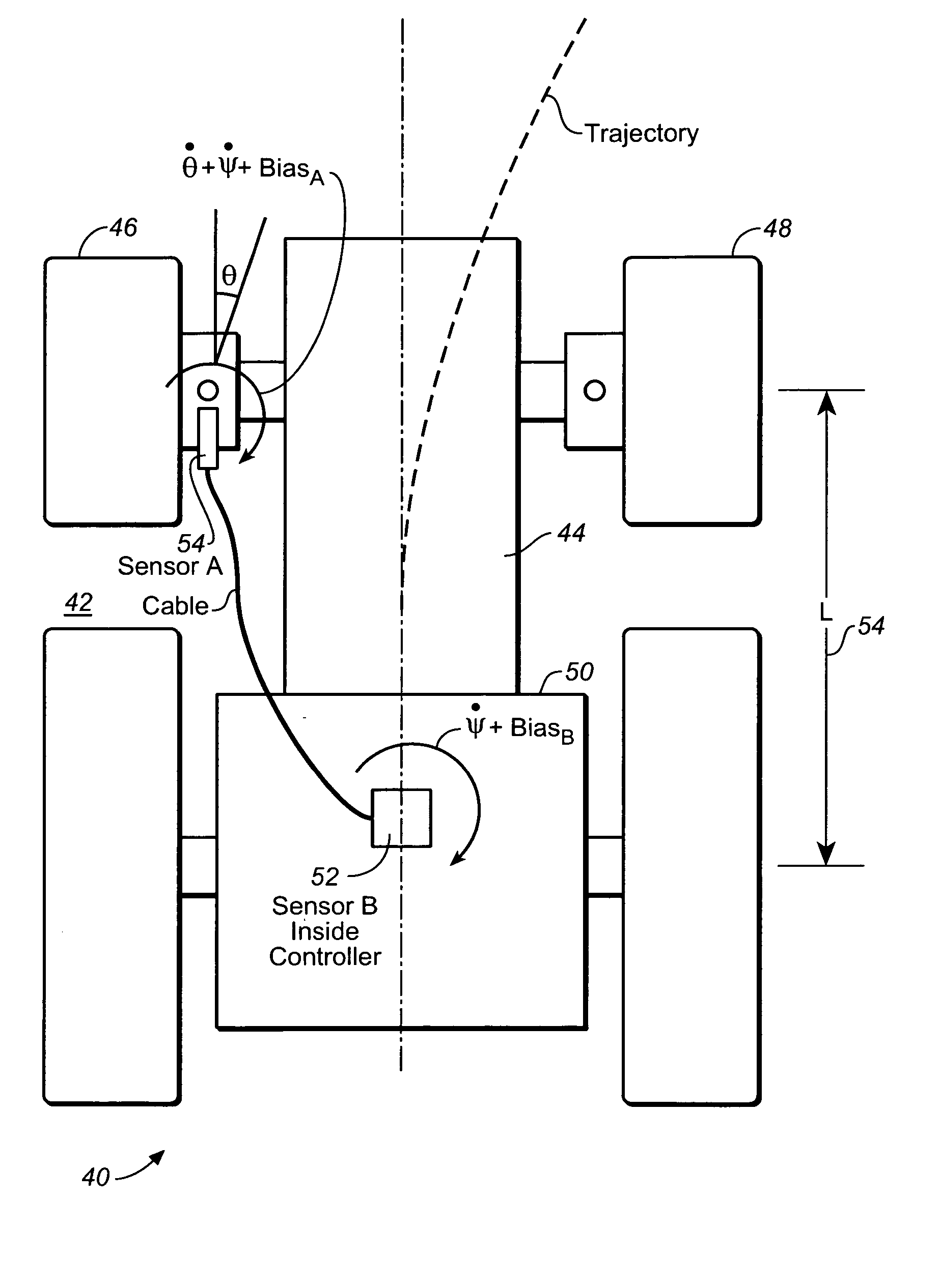
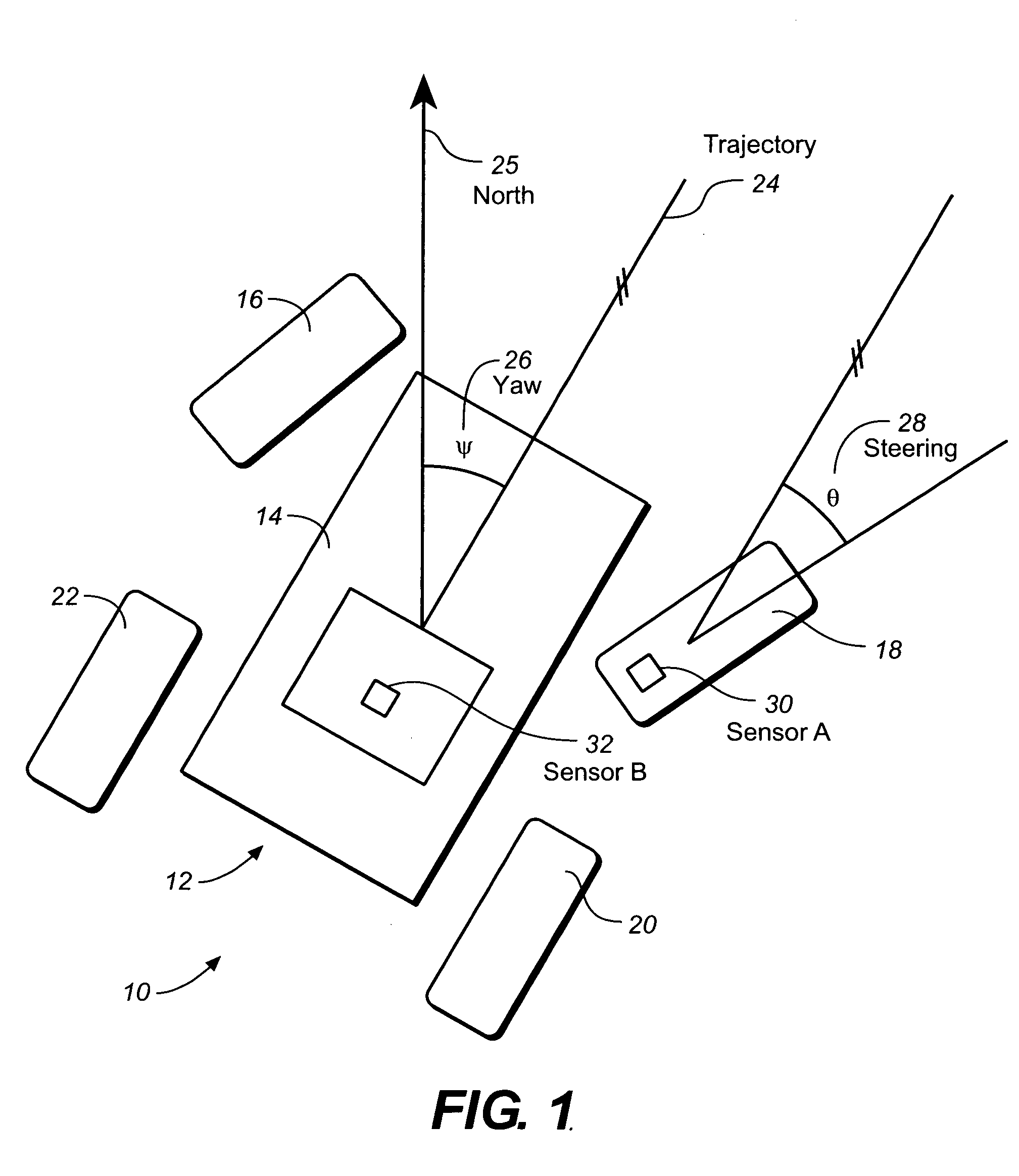
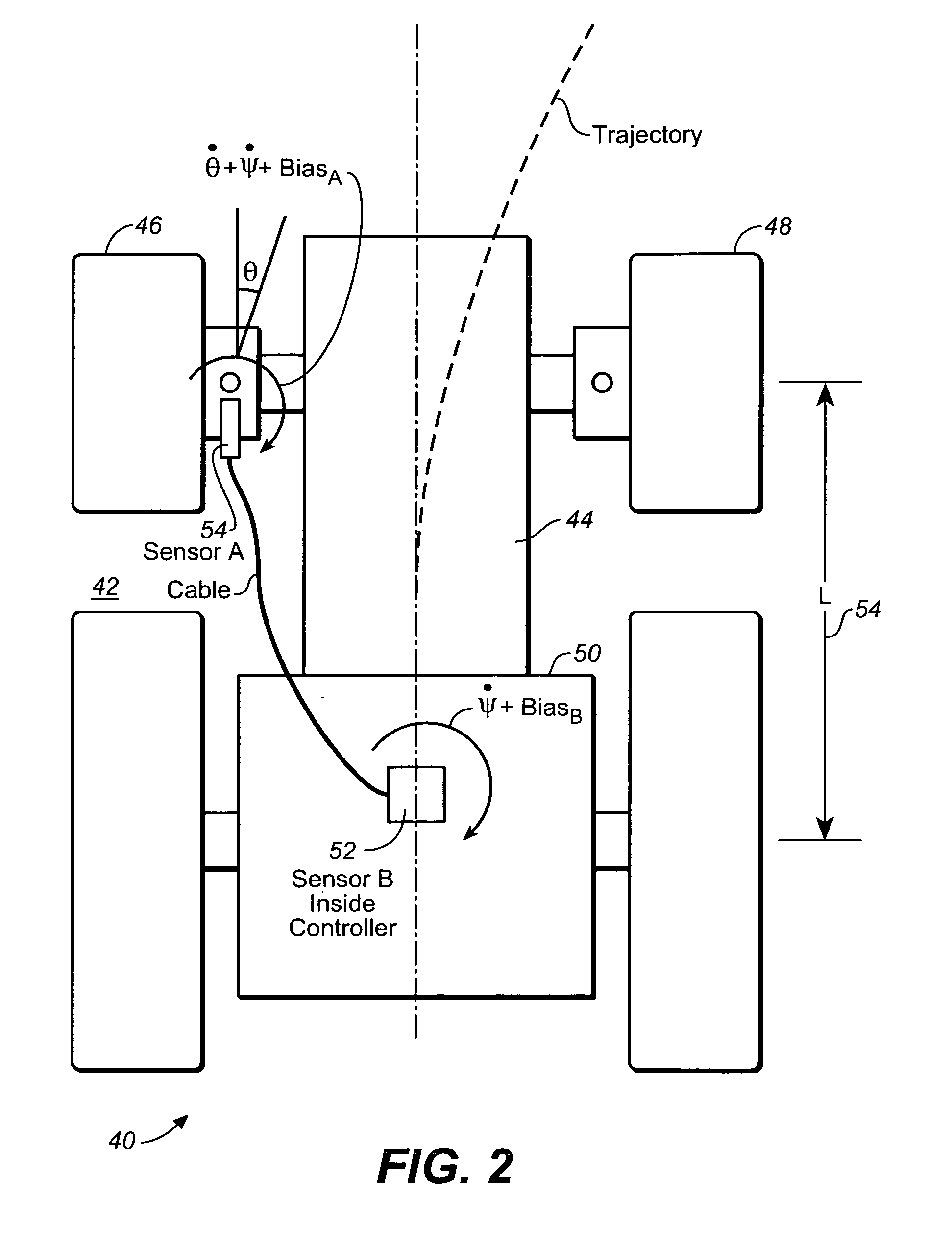
Vehicle Steering Wheel Angle Measurement.

[0077] Sensor A-rate gyroscope attached to one steering front wheel of vehicle, sensing plane parallel to ground. Sensor B —rate gyroscope attached to main body of vehicle, mounted in the same plane (or a combination of gyros with outputs combined in such a way to measure the same plane). Measurement C (see (Esq. 3) is a noisy measurement of steering angle, based on a vehicle's Kinematics behavior. For sensor A, either one sensor + compensation for the Ackerman steering nonlinearity can be used, or the average of two sensors mounted on both steering front wheels to cancel this nonlinearity.

example ii

Excavator Arm Angle Measurement

[0078] Sensor A —a rate gyro mounted on the excavator body. Sensor B—a rate gyro mounted on the excavator arm. Sensor C—a fiducial contact switch making contact when the excavator arm is at its nominal center position.

[0079] Another aspect of the present invention is directed to a method for estimation of relative coordinates between at least two parts of a system.

[0080] In one embodiment, the method of the present invention comprises the following steps (not shown): (A) providing each of at least two parts of the system with at least one coordinate sensor; (B) measuring a set of relevant coordinates for each relevant part of the system; and (C) processing each measurement result performed in the step (B) to estimate the relative coordinates between at least two the parts of the system. In this embodiment of the present invention, the relative coordinates are selected from the group consisting of: {relative position coordinates; relative position r...


PUM


Abstract

A method for estimation of relative coordinates between at least two parts of a system comprising the steps of: (A) providing each of at least two parts of the system with at least one coordinate sensor; (B) measuring a set of relevant coordinates for each part of the system; and (C) processing each measurement result performed in the step (B) to estimate the relative coordinates between at least two parts of the system. The relative coordinates are selected from the group consisting of: {relative position coordinates; relative position rate (velocity) coordinates; relative position acceleration coordinates; relative angle coordinates; relative angular rate coordinates; and relative angular acceleration coordinates}.

Description

BACKGROUND OF THE INVENTION [0001] 1. Field of the Invention [0002] The present invention is in the field of position tracking and machine control systems, and, more specifically, is directed to the field of using position and angular rate sensors for machine control systems. [0003] 2. Discussion of the Prior Art [0004] Rate gyros are well known in the vehicle arts for determining heading and yaw of a vehicle like a car. They are an integral part of improving steering and handling in cars. [0005] More specifically, gyros are commonly used to provide an estimate of a rate of rotation about a particular axis. In wheeled vehicle applications, a gyro can be used to help guide and navigate a wheeled vehicle. In other wheeled vehicle applications, a single-axis gyro is typically used to feed an estimate of yaw rate to a stability control system that is capable of making adjustments to vehicle operation that help increase vehicle stability under a wide variety of operating conditions. [000...

Claims


Application Information

Patent Timeline
IPC IPC(8): B62D6/00
CPCA01B69/008G01C21/165G01C21/16B62D15/024G01C21/1652G01C21/1654G01C21/188
Inventor BREWER, DOUGLAS E.WHITE, GREGORY W.PEAKE, JOHN WILLIAM
Owner TRIMBLE NAVIGATION LTD
Why Eureka
Try Eureka