Plasma producing method and apparatus as well as plasma processing apparatus

a plasma processing and plasma technology, applied in the direction of coatings, electric discharge lamps, electric lighting sources, etc., can solve problems such as defects, and achieve the effect of keeping a low electron temperature in the plasma more readily

Inactive Publication Date: 2007-05-03
NISSIN ELECTRIC CO LTD +1
View PDF10 Cites 11 Cited by
  • Summary
  • Abstract
  • Description
  • Claims
  • Application Information

AI Technical Summary

Benefits of technology

[0018] Accordingly, a first object of the invention is to provide a plasma producing method in which a plurality of high-frequency antennas are arranged in a plasma producing chamber, and an inductively coupled plasma is generated by applying a high-freque

Problems solved by technology

When the electron temperature of the plasma is high when forming the silicon thin f

Method used


Image

  • Plasma producing method and apparatus as well as plasma processing apparatus
  • Plasma producing method and apparatus as well as plasma processing apparatus
  • Plasma producing method and apparatus as well as plasma processing apparatus

Examples


experimental example 1

[0091] (1) Plasma Generation Conditions

[0092] High-frequency Power: Power of 13.56 MHz and 1250 W was supplied to each of the two antennas.

[0093] Plasma Producing Pressure: 1.8 Pa

[0094] Kind and Amount of Supplied Gas: Hydrogen gas, 300 cc / minute

[0095] Initially, the plasma producing chamber was depressurized to the order of 10−5 Pa, then the hydrogen gas was supplied at 300 cc / minute and the chamber pressure was kept at 1.8 Pa.

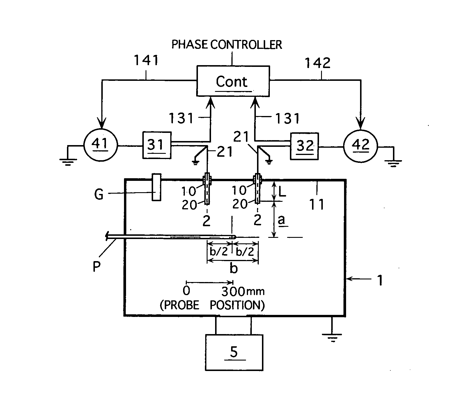
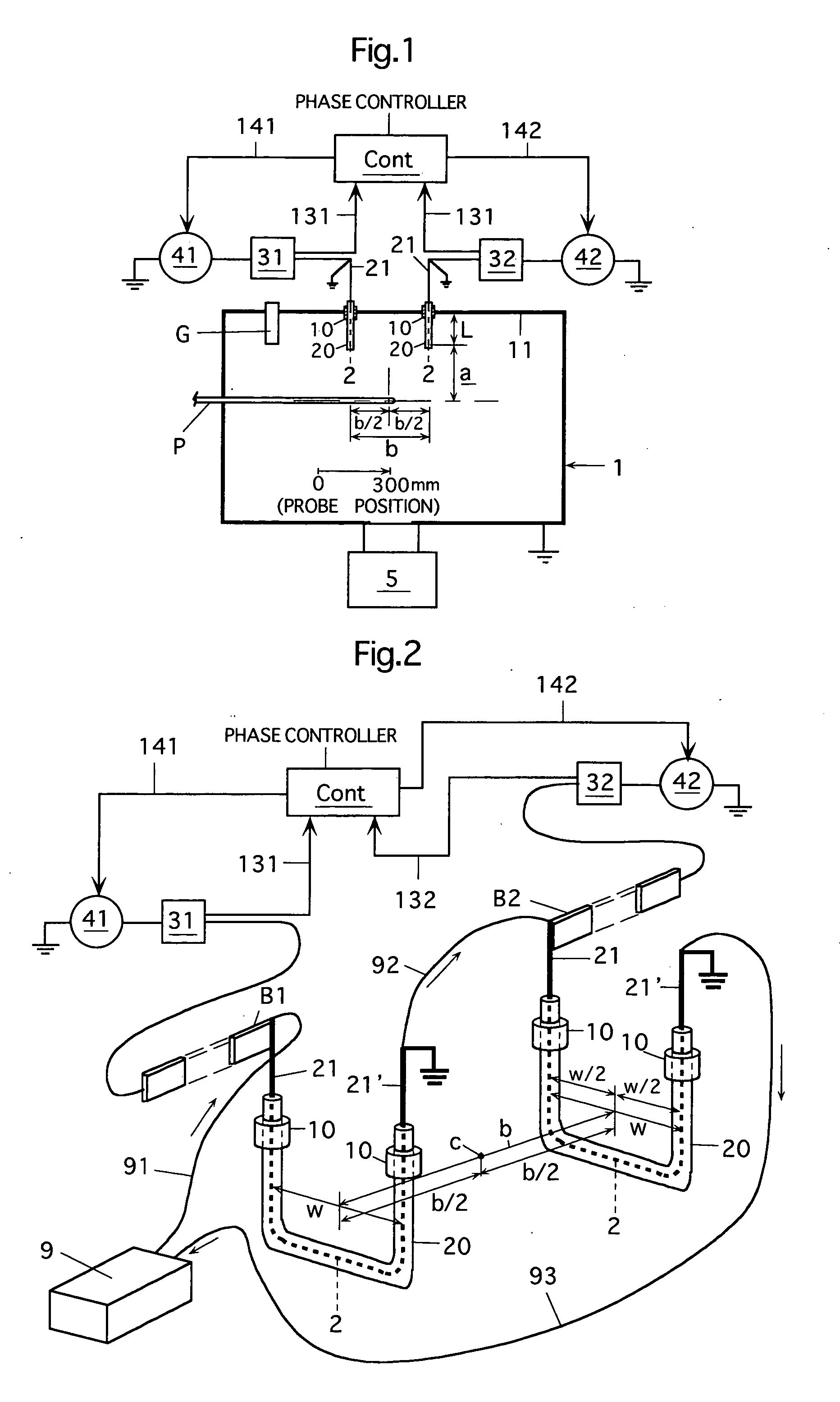
[0096] (2) Antenna and Insulating Tube Conditions

[0097] Material of Each Antenna: A circular copper pipe having an outer diameter of ¼ inch (about 6.35 mm) and a wall thickness of 1 mm was bent into a U-shaped form. Cooling water could flow therethrough.

[0098] Horizontal Width w (see FIG. 2) of Each Antenna: 55 mm

Vertical Length of Each Antenna: 250 mm (Length L in the chamber 1=100 mm)

Distance b between the parallel opposed antennas: b=340 mm

Each Insulating Tube Covering Antenna: Quartz(silica) tube having an outer diameter of 16 mm and an inner d...

experimental example 2

[0107] (1) Plasma Generating Conditions

[0108] These are the same as the conditions in the experimental example 1.

[0109] (2) Antenna and Insulating Tube Conditions

[0110] These are the same as the conditions in the experimental example 1.

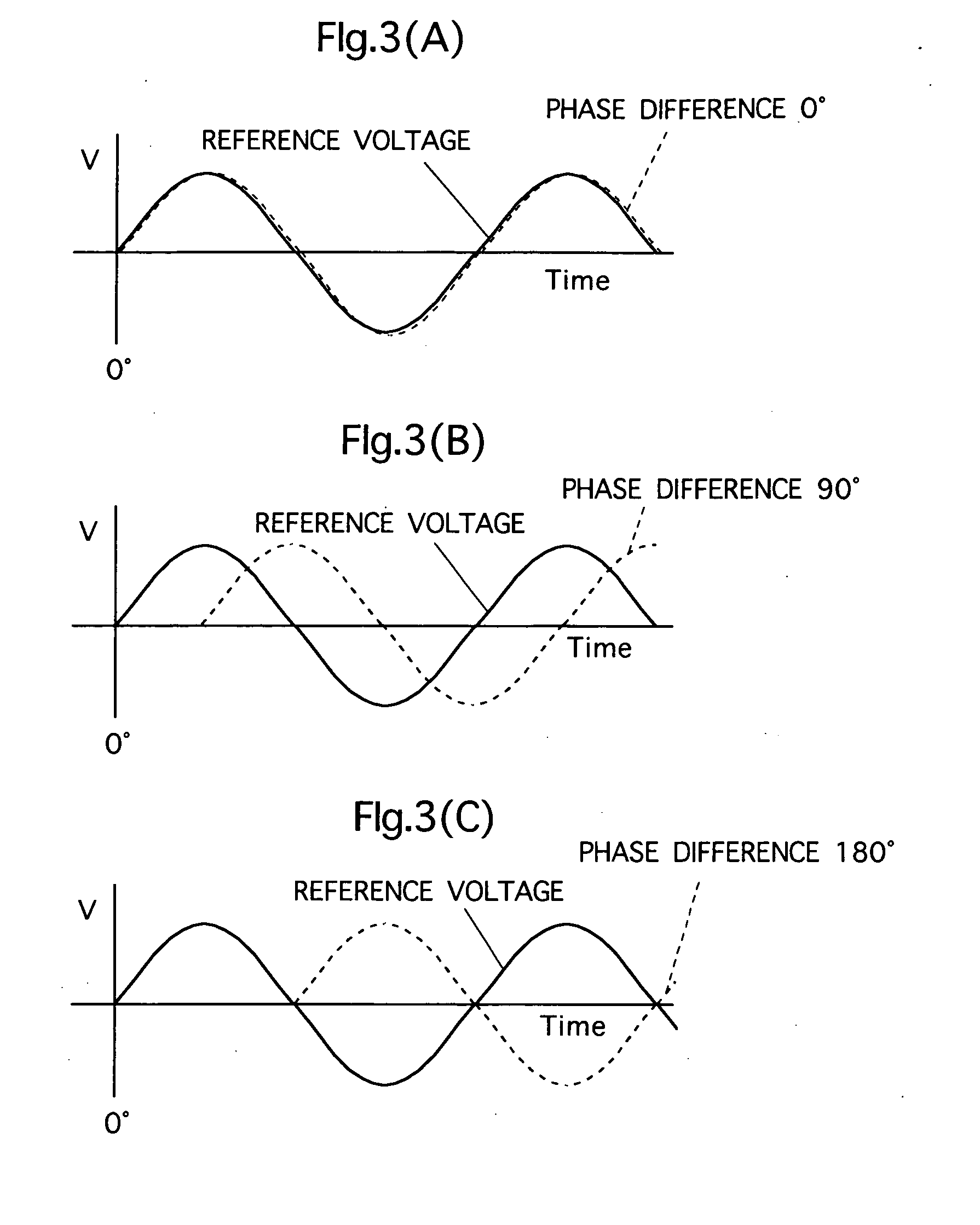
[0111] Under the above conditions, the inductively coupled plasma was produced with the phase differences of 0 degrees, 90 degrees and 180 degrees caused between the high-frequency voltages applied to the two antennas. In connection with each of the phase differences, the electron temperature (eV) and electron--density (pcs / cm3) were measured, and the plasma was evaluated. The measuring method and conditions were the same as those in the experimental example 1.

[0112]FIG. 7 illustrates a result of the measurement of the electron temperature (eV), and FIG. 8 illustrates a result of the measurement of the electron density.

[0113] As can be seen from FIGS. 7 and 8, the lowest electron temperature was attained when the phase difference was 0 degrees. ...


PUM

PropertyMeasurementUnit
Angleaaaaaaaaaa
Angleaaaaaaaaaa
Polarityaaaaaaaaaa

Abstract

Plasma producing method and apparatus wherein a plurality of high-frequency antennas are arranged in a plasma producing chamber, and a high-frequency power supplied from a high-frequency power supply device (including a power source, a phase controller and the like) is applied to a gas in the chamber from the antennas to produce inductively coupled plasma. At least some of the plurality of high-frequency antennas are arranged in a fashion of such parallel arrangement that the antennas successively neighbor to each other and each of the antennas is opposed to the neighboring antenna. The high-frequency power supply device controls a phase of a high-frequency voltage applied to each antenna, and thereby controls an electron temperature of the inductively coupled plasma.

Description

CROSS-REFERENCE TO RELATED APPLICATION [0001] This invention is based on Japanese Patent application No. 2005-313594 filed in Japan on Oct. 28, 2005 and Japanese Patent application No. 2006-178858 filed in Japan on Jun. 29, 2006, the entire contents of which are hereby incorporated by reference. BACKGROUND OF THE INVENTION [0002] 1. Field of the Invention [0003] The invention relates to a plasma producing method and apparatus for producing gas plasma as well as a plasma processing apparatus using the plasma producing apparatus, i.e., a plasma processing apparatus effecting intended processing on a work or target in plasma. [0004] 2. Description of the Related Art [0005] Plasma is used, e.g., in plasma CVD method and apparatus forming a film in plasma, method and apparatus forming a film by effecting sputtering on a sputter target in plasma, method and apparatus performing etching in plasma, and method, apparatus and the like used for performing ion implantation or ion doping by extr...

Claims


Application Information

Patent Timeline
IPC IPC(8): C23C16/00
CPCH01J37/321H01J37/32174H01J37/32954H01J37/32495C23C16/505C23C16/24
Inventor KATO, KENJIDEGUCHI, HIROSHIGEYONEDA, HITOSHIKUBOTA, KIYOSHIEBE, AKINORISETSUHARA, YUICHI
Owner NISSIN ELECTRIC CO LTD
Why Eureka
Try Eureka