Inductive load drive device and drive method

Inactive Publication Date: 2007-05-03
PANASONIC CORP
View PDF0 Cites 4 Cited by
  • Summary
  • Abstract
  • Description
  • Claims
  • Application Information

AI Technical Summary

Benefits of technology

[0010] The present invention therefore shortens the attenuation time of the regenerative current that is produced i

Problems solved by technology

The power supply voltage can therefore exceed the withstand voltage of the inductive load drive device and possibly damage the drive device.
This necessarily increases the

Method used


Image

  • Inductive load drive device and drive method
  • Inductive load drive device and drive method
  • Inductive load drive device and drive method

Examples


Example

First Embodiment

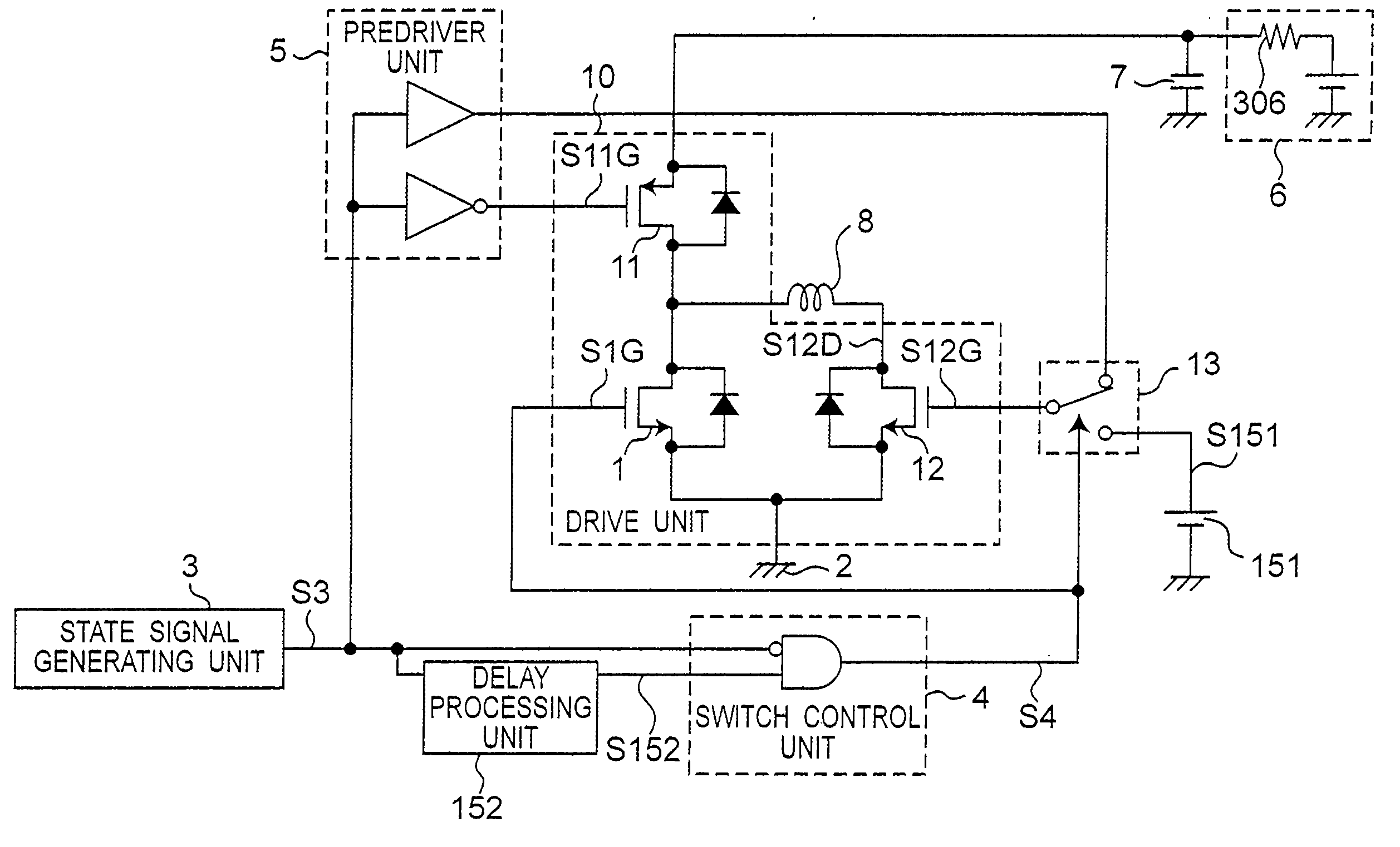
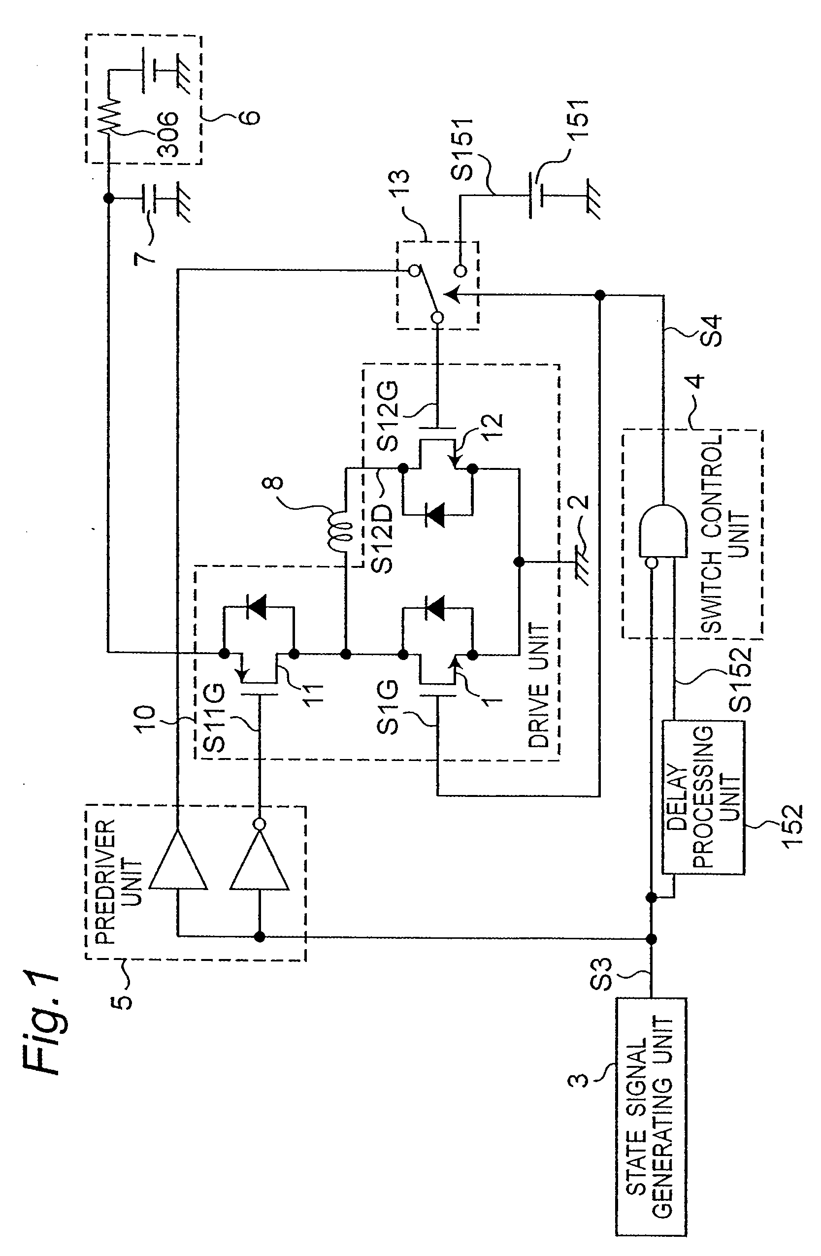
[0040]FIG. 1 is a schematic block diagram of an inductive load drive device according to a first embodiment of the invention.

[0041] An inductive load drive device according to the present invention supplies drive power to an inductive load 8.

[0042] The period when drive power is supplied is called the “drive period” below, and the operating state at that time is called the “drive state.”

[0043] The period when supplying drive power stops and regenerative power from the inductive load 8 is received is called the “regeneration period,” and the operating state at that time is called the “regeneration state.”

[0044] An inductive load drive device according to the invention is a device for driving an inductive load 8 by repeatedly switching between the drive state supplying drive power to the inductive load 8, and the regeneration state receiving drive power from the inductive load 8.

[0045] The inductive load drive device shown in FIG. 1 has a drive unit 10 for supplyin...

Example

Second Embodiment

[0060]FIG. 4 is a schematic block diagram of an inductive load drive device according to a second embodiment of the invention. The first embodiment described above can drive the inductive load 8 in only one direction. This second embodiment differs in being able to drive the inductive load 8 in both forward and reverse directions. This embodiment is described below with particular reference to the differences between this embodiment and the first embodiment.

[0061] Shown in FIG. 4 are the inductive load 8, a drive unit 10 for supplying drive power to the inductive load 8, predriver units 5A and 5B, a power supply 6, a ground 2, a capacitance between the power supply and ground 7, an internal resistance 306 in the power supply, and a phase signal generating unit 9 for generating a phase signal S9 representing forward or reverse phase state information. A state signal generating unit 3 outputs a state signal S3 indicating whether the current operating state is the dr...

Example

Third Embodiment

[0076]FIG. 6 is a schematic block diagram of an inductive load drive device according to a third embodiment of the invention.

[0077] This third embodiment replaces the regenerative gate voltage sources 151A, 151B used in the second embodiment with differential operators 21A and 21B and first reference voltage sources 22A and 22B. The differential operators 21A and 21B are differential amplifiers, for example. The first reference voltage sources 22A and 22B output a predetermined first reference voltage S22A and S22B, respectively.

[0078] This embodiment is described below with particular reference to the differences between this embodiment and the second embodiment.

[0079] In the normal phase drive state, the phase signal S9 and state signal S3 are LOW, the high potential side switching unit 11A is ON, and the high potential side switching unit 11B is OFF. The switch control signals S4A and S4B are LOW, the switches 13A and 13B are set to the predriver units 5A and ...


PUM


Abstract

An inductive load drive device for driving an inductive load shortens the attenuation time of the regenerative current produced in the inductive load without increasing capacitance between the power supply and ground. A drive signal generating unit produces a drive signal denoting a logic level of the drive state and regeneration state. A drive unit is controlled based on the drive signal to an OFF state, a high resistance ON state having a high ON resistance, or a low resistance ON state having a low ON resistance, to produce the drive power. The drive unit has a high potential side switching unit group and a low potential side switching unit group. In the regeneration state either the high potential side switching unit group or the low potential side switching unit group is OFF and at least one switching unit of the other switching unit group is on.

Description

BACKGROUND OF THE INVENTION [0001] 1. Field of Invention [0002] The present invention relates to technology for shortening the regenerative current attenuation time and reducing capacitance between the power supply and ground in an inductive load drive circuit that can drive an inductive load in a single direction or in both normal and reverse directions. [0003] 2. Description of Related Art [0004] Inductive load drive devices are used, for example, to drive the mechanical shutter in digital cameras, and shortening the time required for forward / reverse phase switching of the inductive load is desired. Reducing the forward / reverse phase switching time requires shortening the attenuation time of the regenerative current that is produced in the inductive load when the phase is switched. Japanese Unexamined Patent Appl. Pub. H5-268036 teaches an inductive load drive circuit that addresses this problem as described below with reference to FIG. 19. [0005] The inductive load drive circuit ...

Claims


Application Information

Patent Timeline
IPC IPC(8): H01H47/00
CPCH03K17/04123H03K17/08104H03K17/6872H03K2217/0036
Inventor SHIROKOSHI, HIDEKI
Owner PANASONIC CORP
Why Eureka
Try Eureka