
Air supply apparatus

a technology of air supply and apparatus, which is applied in the field of air supply system, can solve the problems of poor actual results of uvc system to date, inability to evaluate or determine the success of air sterilization system, and inability to measure low pathogen concentrations in prior art systems, and achieve the effect of constant pressur

Inactive Publication Date: 2007-05-10
NEXT SAFETY INC
View PDF0 Cites 71 Cited by
  • Summary
  • Abstract
  • Description
  • Claims
  • Application Information

AI Technical Summary

Benefits of technology

[0028] Still further, according to the invention, there is provided a method of providing protection against airborne pathogens, comprising (a) providing a face mask for channeling air to a user, and (b) sterilizing the air that is channeled to the user, using UV radiation. The method may include sterilizing the air exhaled by said user. The method may include controlling the flow rate or pressure of air channeled to the user. The peressure may be controlled to maintain substantially constant pressure during inhaling and exhaling by the user and during changes in exertion by the user. The air stream provided by the blower / fan / pump or the pressure may be controlled by controlling at least one of a flapper valve and the blower, fan or pump.

Problems solved by technology

The third reason, however, suggests that actual results in UVC systems to date have been poor; since all known systems have utilized a design where air flows past a round lamp having a photon flux that varies dramatically based on the lamp radius and the distance from the lamp.
Most importantly, prior art systems have not provided an evaluation or determination of the success of air sterilization systems and have made no attempts at measuring low pathogen concentrations.
The fact that these systems have dramatic variations in effectiveness as shown both in demonstations and through the use of models means that secondary effects such as k2 that were measured on a planar surface have not been addressed in prior art systems.
However, in the case of pumps, blowers or fans mounted in a housing or conduit in order to move air through the housing or conduit, no known system automatically adjusts power to the pump, blower or fan or adjust shutters or other mechanisms such as a butterfly valves in order to achieve constant flow or constant pressure as external factors vary and therefore seek to impact the flow rate or air pressure.
However, the prior art systems making use of UV sources to kill biological contaminants in air do not consider controlling the flow rate past the UV radiation source in order to control the UV dosage to which the contaminants are exposed or controlling the pressure in a kill or sterilization chamber.
More particularly, they do not consider moving the air past a UV source using a pump, fan or blower and adjusting the flow rate of the air by adjusting power to the pump, fan or blower.
Thus the prior art also does not consider power saving, by automatically adjusting power to the pump, fan or blower in response to changing demands, which is particularly important in portable devices.
Furthermore, the prior art systems do not ensure that biological contaminants passing through a kill or sterilization chamber or through a sterilization zone, e.g., a UV radiation zone provided in an air duct system of a house, ship or aircraft, receive an adequate amount of radiation to render them harmless.
Nor do they optimize power usage in portable devices, or consider the possible harmful byproducts of UV radiation, such as ozone and carbon monoxide.
Also there is no art that teaches actively destroying biological contaminants in a face mask assembly using ultraviolet radiation.

Method used


Image

  • Air supply apparatus
  • Air supply apparatus
  • Air supply apparatus

Examples


Embodiment Construction

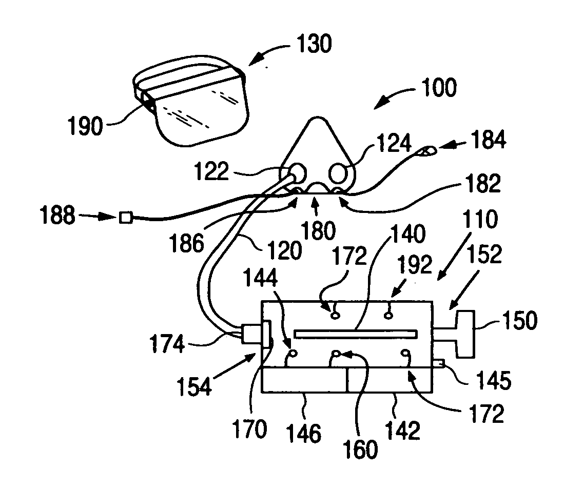
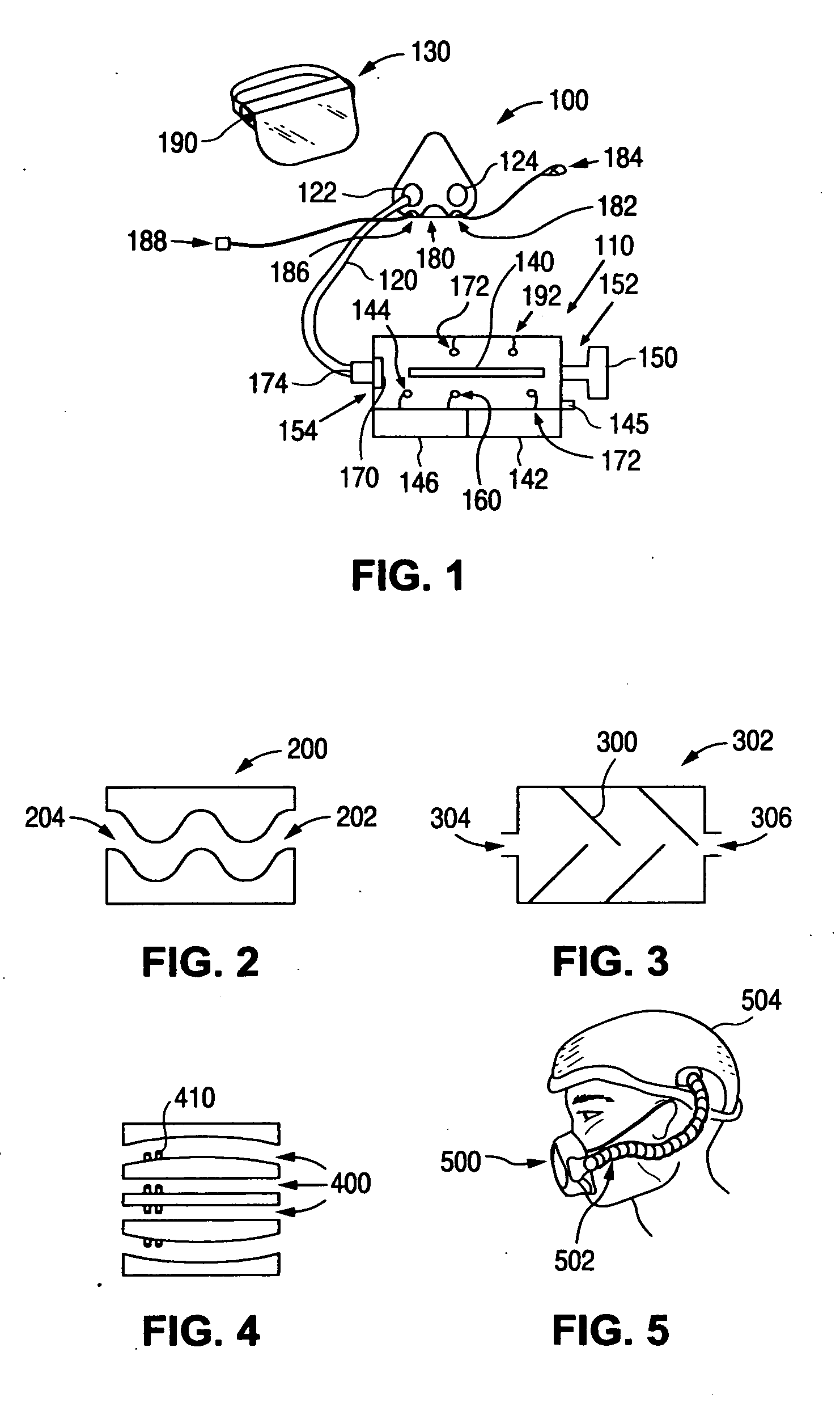
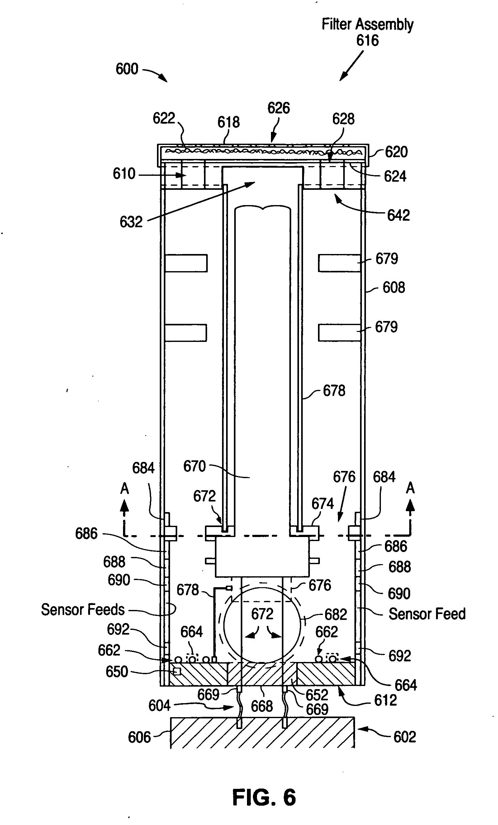
[0067] As mentioned above, the present invention defines an air supply system providing an air stream, the system including a filter and a means for moving the air, e.g., a pump, fan, or blower, as well as means for controlling either the flow rate of the air stream or the air pressure. In contrast, prior art devices make use of constant high flow rates which prevents use of good HEPA filters due to the large pressure drop. Also, they produce a large positive pressure causing constant expulsion of air and are therefore typically used with visor-like masks that allow air to freely pass from the mask. Since they are not on-demand systems they will potentially expose the user to more contaminated air. The present invention, on the other hand, makes use of a controlled air flow system to avoid these drawbacks. The embodiments of the present application, further include means for killing or destroying organic contaminants in the air stream by radiating the air stream with UV radiation.

[...


PUM


Abstract

In an air sterilization system that includes a UV kill chamber for sterilizing air that is to be supplied to users, the effectiveness of killing or neutralizing pathogens is increased by including not only a UV light source of a certain intensity but also including a particle filter and providing short duration high intensity UV radiation. In the case of a user specific system that includes a face mask to supply air to a specific user, exhaled air from the face mask may be sterilized as well, either by using the same kill chamber or by using a separate kill chamber.

Description

[0001] This is a continuation-in-part of U.S. application Ser. No. 11 / 268,936 to Charles Eric Hunter, filed Nov. 8, 2005; of Ser. No. 11 / 317,045 to Charles Eric Hunter filed Dec. 23, 2005; of the patent application Ser. No. 11 / 412,231 entitled “Air Supply Apparatus” filed Apr. 26, 2006, and of provisional patent application 60 / 796,368 entitled “Air Supply Apparatus” filed May 1, 2006.FIELD OF THE INVENTION [0002] The invention relates to an air supply system and applications of the air supply system to kill airborne organisms such as viruses, bacteria and fungi, also referred to as organic material, pathogens or biological contaminants using ultraviolet (UV) radiation. For purposes of this application the term “killing” also includes any DNA or RNA destruction. BACKGROUND OF THE INVENTION [0003] In order to provide an effective sterilization respirator based on UV sterilization the present application recognizes the need to take into account air consumption rates by the user. The pr...

Claims


Application Information

Patent Timeline
IPC IPC(8): C07C1/00B01J19/12
CPCA61L9/16A61L9/205B01D53/007B01D2257/91
Inventor HUNTER, C. ERICHUNTER, JOCELYN L.BALLOU, BERNARD L. JR.HEBRANK, JOHN H.MCNEIL, LAURIE E.
Owner NEXT SAFETY INC
Learn More