Abnormality detection apparatus for a power feed circuit

Active Publication Date: 2007-05-10
MITSUBISHI ELECTRIC CORP
View PDF1 Cites 32 Cited by
  • Summary
  • Abstract
  • Description
  • Claims
  • Application Information

AI Technical Summary

Benefits of technology

[0009] Accordingly, the present invention is intended to obviate the problems as referred to above, and has for its object to provide an abnormality detection apparatus for a power feed circuit which is capable of detecting an open-circuit state a

Problems solved by technology

According to the conventional abnormality detection apparatus for a power feed circuit, for example, in the case of the intelligent power switching device as described in the above-mentioned first patent document, the energization of an overheat self-hold type semiconductor switch (power transistor) connected to a downstream side of the electric load is interrupted upon occurrence of an overcurrent, but no particular reference is made

Method used


Image

  • Abnormality detection apparatus for a power feed circuit
  • Abnormality detection apparatus for a power feed circuit
  • Abnormality detection apparatus for a power feed circuit

Examples


Example

Embodiment 1.

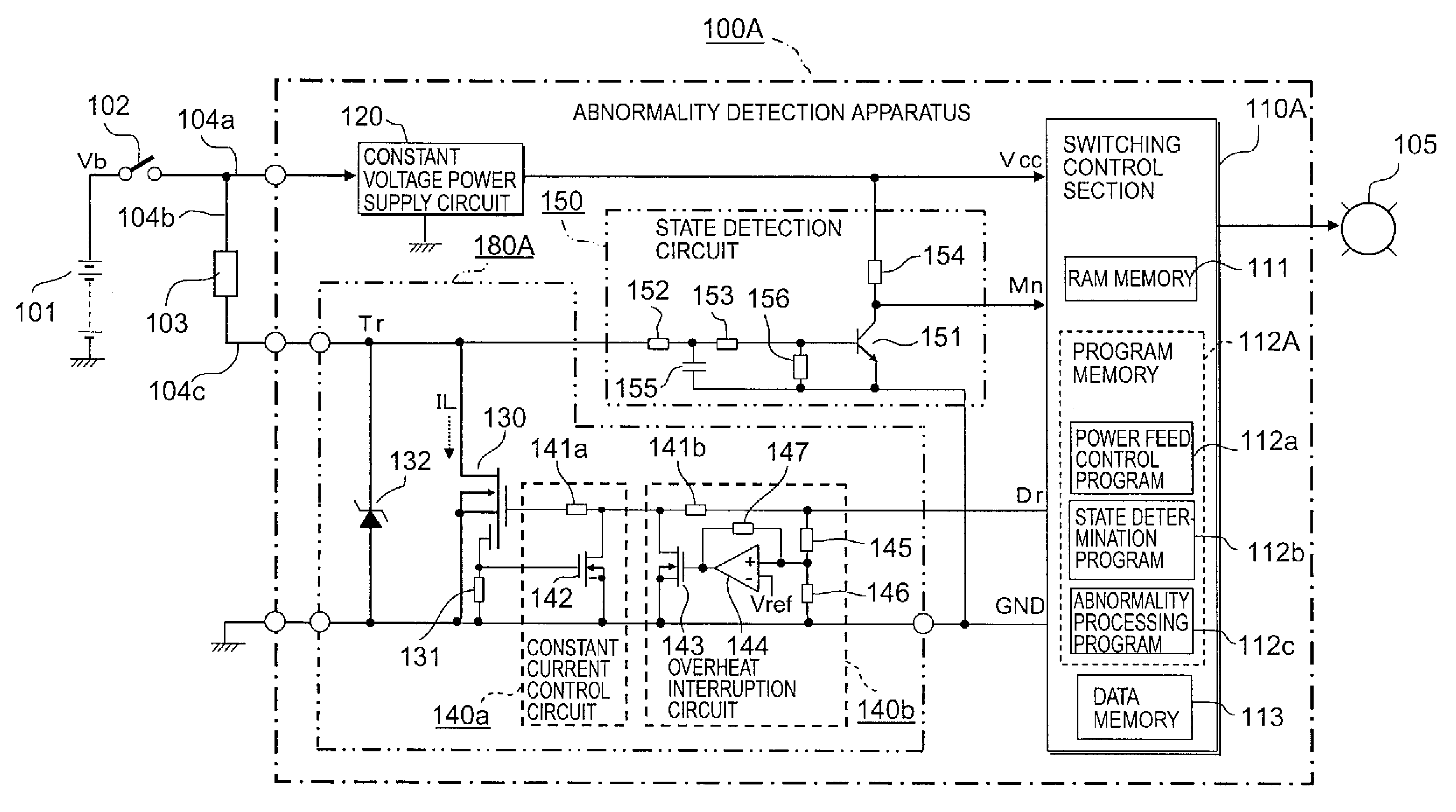
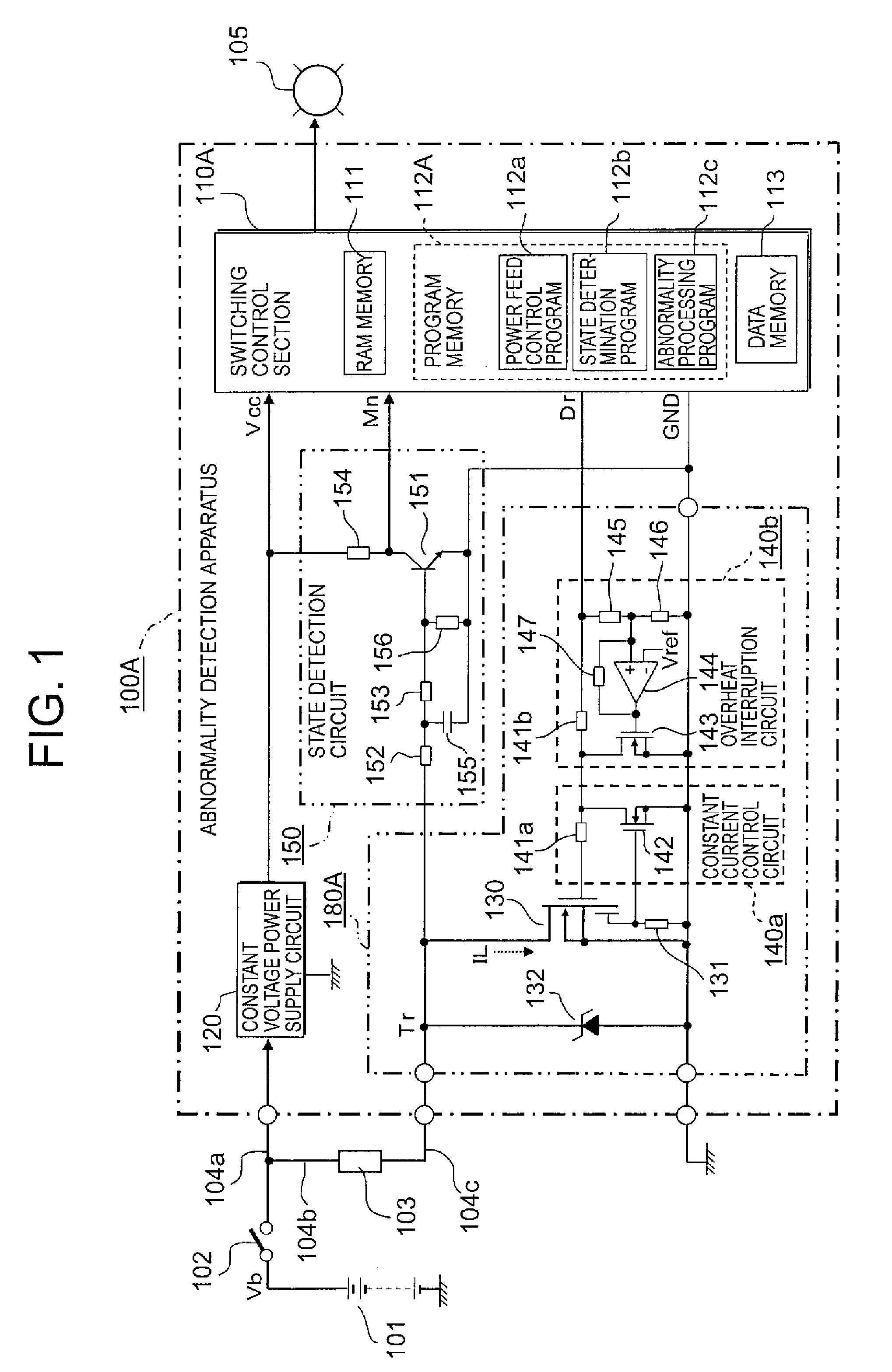
[0023] First, reference will be made to an abnormality detection apparatus for a power feed circuit according to a first embodiment of the present invention. FIG. 1 is a circuit block diagram that shows the overall configuration of the abnormality detection apparatus for a power feed circuit according to the first embodiment of the present invention.

[0024] In FIG. 1, the abnormality detection apparatus, generally designated at 100A, constitutes, in a concrete sense, an automotive engine control apparatus, and is fed power from a DC power supply 101 in the form of an on-board battery through a power switch 102 such as a key switch, etc., and a power supply line 104a.

[0025] In addition, an electric load 103 is composed, for example, of an electromagnetic coil for driving an electromagnetic valve for emission control in an automotive engine control unit, and is connected to the abnormality detection apparatus 100A. The electric load 103 is connected to the power supply...

Example

[0109] Although in the above-mentioned first embodiment (FIG. 1), the state detection circuit 150 is constructed separately from the power module 180A, a state detection circuit 170 may be built in a power module 180B, as shown in FIG. 6.

[0110] Hereinafter, reference will be made to an abnormality detection apparatus for a power feed circuit according to a second embodiment of the present invention while referring to FIG. 6.

[0111]FIG. 6 is a block diagram that illustrates the overall configuration of the abnormality detection apparatus for a power feed circuit according to the second embodiment of the present invention, wherein the same parts or components as those described above (see FIG. 1) are identified by the same symbols or by the same symbols with “B” affixed to their ends, while omitting a detailed explanation thereof.

[0112] In FIG. 6, the abnormality detection apparatus, generally designated at 100B, specifically constitutes a control unit of an automotive transmission,...


PUM


Abstract

A single state detector circuit can quickly detect short-circuit and open-circuit abnormalities of a load controlled by a power transistor. A DC power supply, the load and the power transistor are serially connected with one another, so that a switching terminal voltage of the power transistor is binarized into high and low levels by the state detector. The power transistor is linearly controlled by a constant-current control circuit so as to suppress an excessive current, and power supplied to the power transistor is interrupted by an overheat interruption circuit. Upon occurrence of a short-circuit in the load during generation of an energization command, a switching terminal voltage of the power transistor becomes stabilized at a high level without intermittent operation, which is detected by the state detector. Upon occurrence of an open-circuit during generation of a deenergization command, a low switching terminal voltage is detected by the state detector.

Description

BACKGROUND OF THE INVENTION [0001] 1. Field of the Invention [0002] The present invention relates to an abnormality detection apparatus for a power feed circuit that is built in a vehicle-mounted electronic control apparatus (an engine control apparatus, a transmission control apparatus, etc.), and more particularly, it relates to such an abnormality detection apparatus for a power feed circuit in which a power transistor for controlling the supply of power to an electric load has an overcurrent limiting function and an overheat interruption function, and which can identify and determine the presence or absence of an open-circuit abnormality and a short-circuit abnormality of the electric load in a quick manner. [0003] 2. Description of the Related Art [0004] In general, in power feed control on an electric load, there have been widely put into practical use intelligent power switching devices having a power transistor, an overcurrent limiting function and an overheat interruption f...

Claims


Application Information

Patent Timeline
IPC IPC(8): H01H83/10H01H35/00H02H3/20
CPCH03K17/0822H03K17/18H03K17/687H03K2017/0806
Inventor ZUSHI, YUJIKANZAKI, SHOZO
Owner MITSUBISHI ELECTRIC CORP
Why Eureka
Try Eureka