Fiber optic gyroscope asynchronous demodulation

Active Publication Date: 2007-05-10
HONEYWELL INT INC
View PDF11 Cites 14 Cited by
  • Summary
  • Abstract
  • Description
  • Claims
  • Application Information

AI Technical Summary

Benefits of technology

[0015] The present invention thus provides a clock system and method that can achieve both the tunability objective of the bias modulation clo

Problems solved by technology

Furthermore, they can be highly sensitive to very low rotation rates that can be a problem in other kinds of optical gyroscopes.
The resulting path length difference results in a phase shift between the waves propagating in opposite directions.
Specifically, waves propagating in opposite directions interfere when recombined and impinge upon photodetector, which measure the intensity of the combined wave.
Quadrature errors are unwanted signals that are synchronous with the desired rate signal but are 90 degrees out of phase with the rate signal.
The two most common and significant quadrature errors in an fiber optic gyroscope are due to intensity modulation and second harmonic phase modulation (or any even harmonics) generated by the bias phase modulation.
Even if the bias modulation exac

Method used


Image

  • Fiber optic gyroscope asynchronous demodulation
  • Fiber optic gyroscope asynchronous demodulation
  • Fiber optic gyroscope asynchronous demodulation

Examples


Embodiment Construction

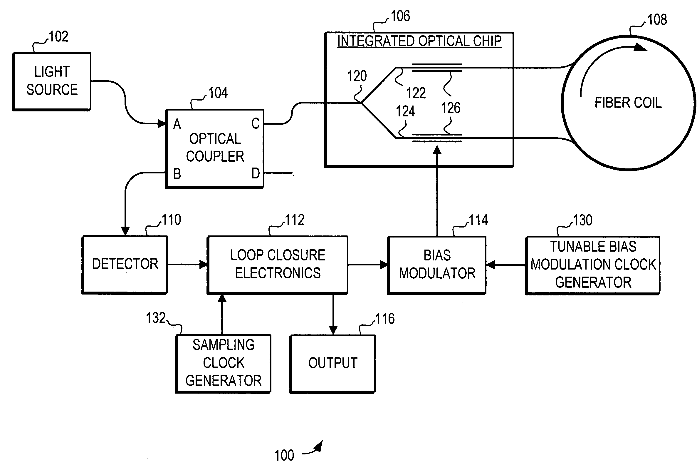
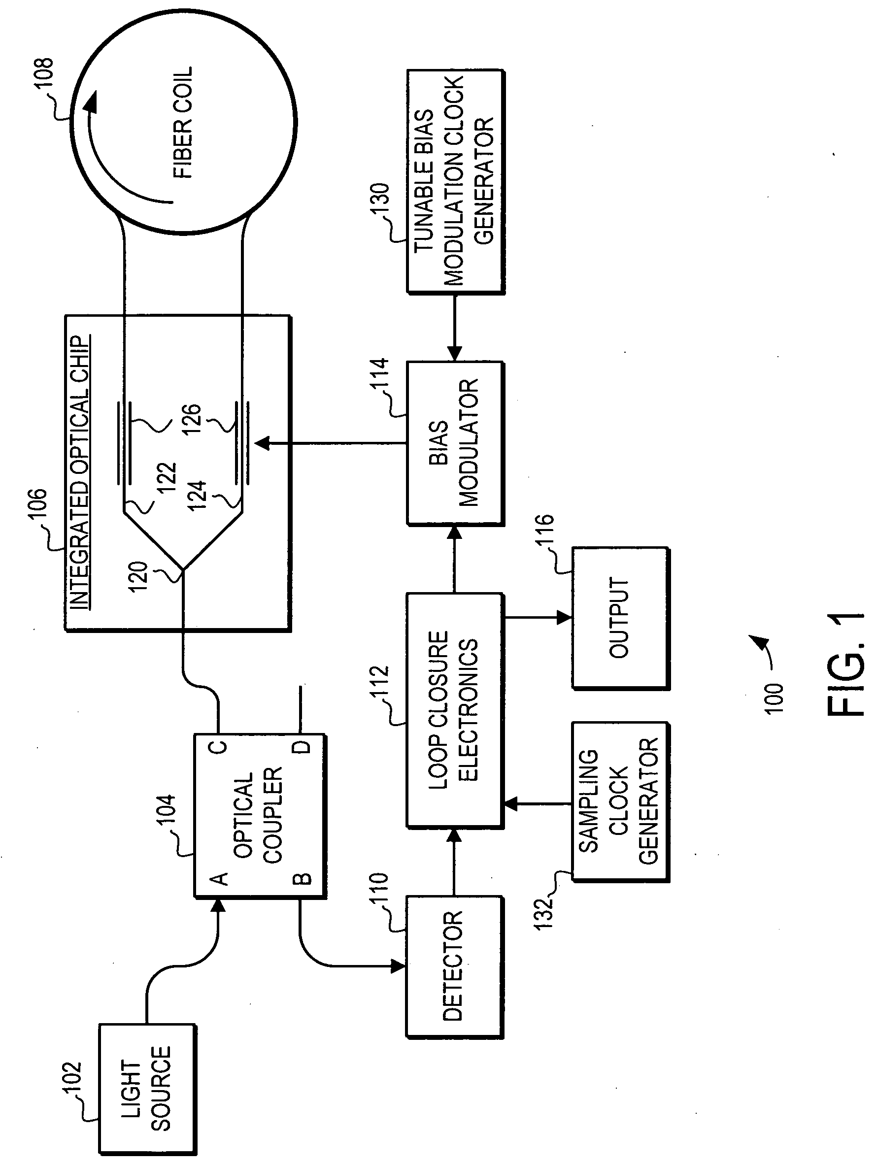
[0022] The present invention provides a clock system and method for a fiber optic gyroscope that includes a highly-tunable clock for the bias modulation and a separate asynchronous high-speed clock for the photodetector sampling. By separating the two clocks rather than using two derivatives of the same clock, the clock system and method can provide both the tunability objective of the bias modulation clock and the high-speed objective of the sampling clock, while using readily available, lower performance, radiation-hardened electronics parts.

[0023] The preferred embodiment system for creating the tunable low-speed clock for the bias modulation uses a direct digital synthesis (DDS) circuit. A DDS circuit is comprised of a digital sine wave generator, a digital-to-analog converter (DAC), an analog filter, and a comparator. The DDS circuit generates a clock signal with a highly tunable frequency and thus is suitable for use as a bias modulation clock in a fiber optic gyroscope. In a...


PUM


Abstract

A clock system for a fiber optic gyroscope is provided that includes a highly-tunable clock for the bias modulation and a separate asynchronous high-speed clock for the photodetector sampling. By separating the two clocks rather than using two derivatives of the same clock, the clock system and method can provide both the tunability objective of the bias modulation clock and the high-speed objective of the sampling clock, while using readily available, lower performance, radiation-hardened electronics parts.

Description

STATEMENT REGARDING FEDERALLY SPONSORED RESEARCH OR DEVELOPMENT [0001] This invention was made with Government support under Contract N0030-04-C-0010 awarded by the Department of the Navy and under Contract F29601-03-0124 awarded by the Air Force Research Lab. The Government has certain rights in this invention.FIELD OF THE INVENTION [0002] This invention generally relates to fiber optic gyroscopes, and more specifically relates to timing in fiber optic gyroscopes. BACKGROUND OF THE INVENTION [0003] Fiber optic gyroscopes are used to accurately sense rotation of an object supporting such a gyroscope. Fiber optic gyroscopes can be made quite small and can be constructed to withstand considerable mechanical shock, temperature change, and other environmental extremes. Due to the absence of moving parts, they can be nearly maintenance free. Furthermore, they can be highly sensitive to very low rotation rates that can be a problem in other kinds of optical gyroscopes. [0004] A typical fi...

Claims


Application Information

Patent Timeline
IPC IPC(8): G01C19/72G01C19/66
CPCG01C19/721
Inventor GREENING, THOMAS C.LANGE, CHARLES H.CHEN, CHUNG-JEN
Owner HONEYWELL INT INC
Why Eureka
Try Eureka