Nanostructured core-shell electrocatalysts for fuel cells

Inactive Publication Date: 2007-05-10
KENT STATE UNIV
View PDF34 Cites 32 Cited by
  • Summary
  • Abstract
  • Description
  • Claims
  • Application Information

AI Technical Summary

Problems solved by technology

The situation looks even less promising in the case of automotive DMFCs.
The high cost of PEFCs is not the only problem that impedes their broad use; the scarcity of Pt metal is even a larger concern.
The first is a poor utilization of Pt nanoparticle

Method used


Image

  • Nanostructured core-shell electrocatalysts for fuel cells
  • Nanostructured core-shell electrocatalysts for fuel cells
  • Nanostructured core-shell electrocatalysts for fuel cells

Examples


Embodiment Construction

[0019] In order to give the reader a better understanding of the proposed design, we will review briefly the historical development and the current designs of the PEFC catalytic layers.

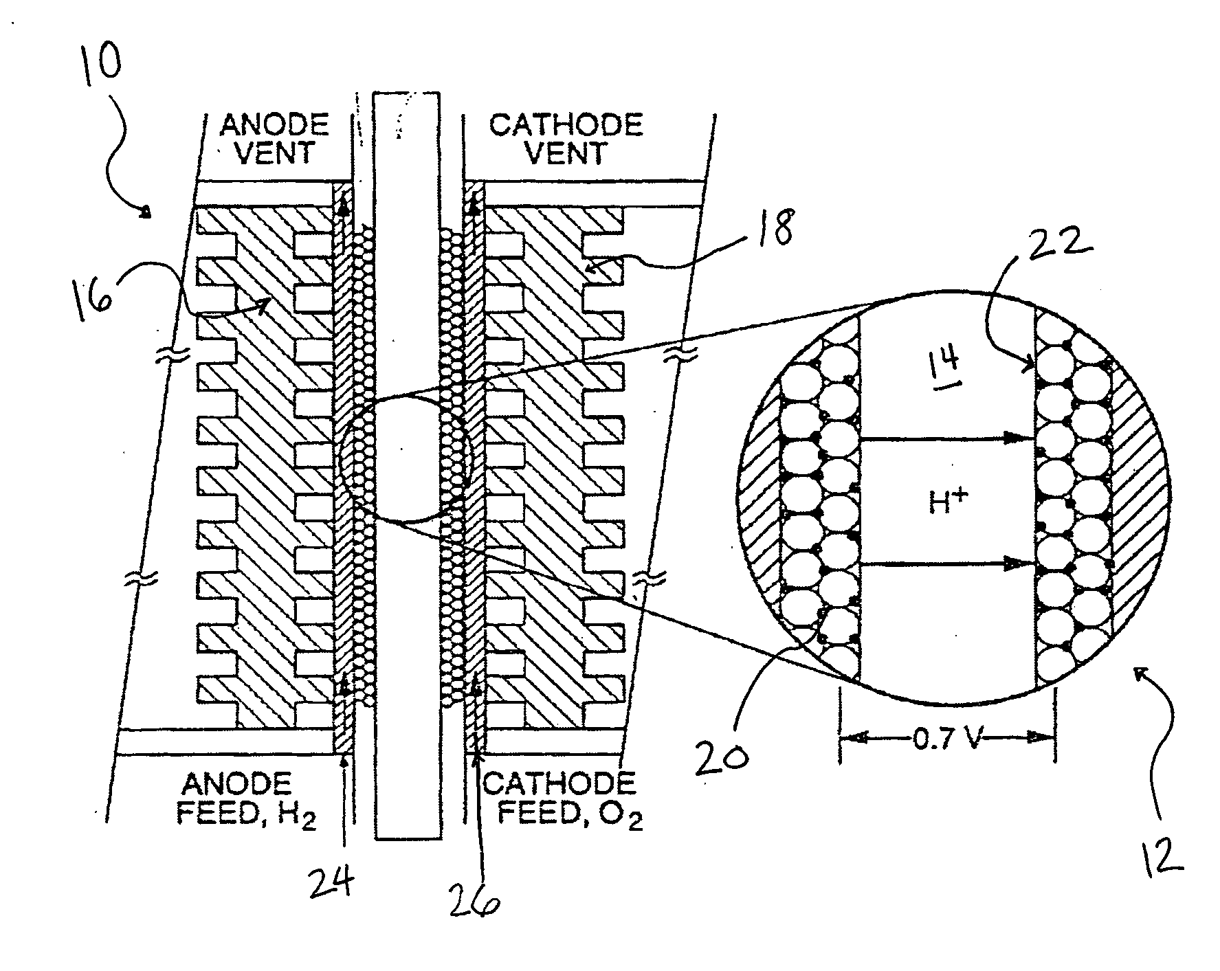
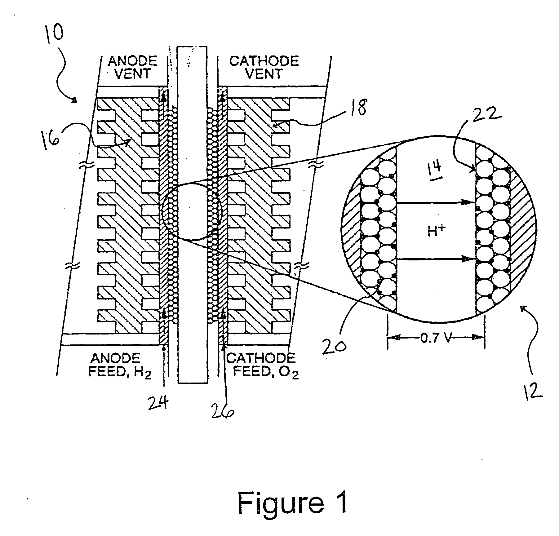
[0020]FIG. 1 shows a schematic diagram of a single stack of a conventional HAFC 10. The heart of the PEFC is a Membrane-Electrode Assembly (MEA) 12, which includes an ion-conducting layer 14 separating an anode and a cathode 16, 18 coated with catalytic layers 20, 22, and sandwiched between two gas diffusion layers 24, 26. Although not intended to be limiting as other electrolytes are also useful in the present embodiments, an exemplary ion-conducting membrane for use herein is Nafion®. Nafion® is a perfluorinated polymer available from DuPont containing a certain proportion of sulfonic acid functional groups and having the general structure below, with H+ being the counter ion:

[0021] Structural optimization of all MEA components is important for maximizing the power density of a fuel cell, but, si...


PUM

PropertyMeasurementUnit
Pore sizeaaaaaaaaaa
Pore sizeaaaaaaaaaa
Thicknessaaaaaaaaaa

Abstract

Catalytic layers for use in the electrodes of fuel cells including a non-noble metal substrate layer coated with one or a few monolayers of noble metal, such as Pt. These thin, highly porous structures with large catalytically active surface areas, should exhibit a significantly higher power output per mg of Pt and per cm2 of the membrane than the current Polymer Electrolyte Fuel Cells catalytic layers.

Description

BACKGROUND [0001] The present exemplary embodiments relate to nanostructured catalyst layers. It finds particular application in conjunction with Polymer Electrolyte Fuel Cells (PEFCs), and will be described with particular reference thereto. However, it is to be appreciated that the present exemplary embodiment is also amenable to other like applications. [0002] Polymer Electrolyte Fuel Cells (PEFCs) are usually fueled with hydrogen or methanol. The hydrogen-air fuel cell (HAFC) is currently considered as the power source of choice for vehicular applications thanks to its superb power density, lifetime and short start-up time. Due to problems with hydrogen storage, another type of PEFC, Direct Methanol Fuel Cell (DMFC), is also investigated for portable and vehicular applications. DMFCs have already entered the market for portable applications, such as military radio stations and laptop computers. [0003] Since PEFCs typically operate at temperatures below 100° C., they require cata...

Claims


Application Information

Patent Timeline
IPC IPC(8): H01M4/86H01M4/92H01M8/10H01M4/88B05D5/12B01J23/38B22F1/17
CPCB22F1/0025B22F1/025B22F2998/00B82Y30/00H01M4/8605H01M4/8657H01M4/8885H01M4/92H01M8/1011H01M8/1023H01M8/1039Y02E60/523C25C5/02C22C1/08Y02E60/50B22F1/0547B22F1/17
Inventor TOLMACHEV, YURIY VIACHESLAVOVICH
Owner KENT STATE UNIV
Why Eureka
Try Eureka