
Multi-source ambient energy power supply for embedded devices or remote sensor or RFID networks

Inactive Publication Date: 2007-05-17
LANGLEY JOHN B II +2
View PDF22 Cites 57 Cited by
  • Summary
  • Abstract
  • Description
  • Claims
  • Application Information

AI Technical Summary

Benefits of technology

[0005] To solve the need for a power supply for an associated energy-using device that can be deployed anywhere and is self-sustaining, reliable and maintenance-free over its service life in potentially harsh conditions, the present invention provides an ambient electromagnetic energy collector that couples to an ambient electromagnetic field around the device to extract energy from the ambient electromagnetic field, having an inductor structure for coupling to a magnetic field component of the ambient electromagnetic field so that it can be substantially reduced in size as compared to an antenna structure for coupling to the electric field component of the ambient electromagnetic field.
[0010] This invention also includes a “smart switch” that can be used to trigger power release from the energy storage component of the ambient energy collector and power supply device for supplying power on demand to the associated energy-using device. This triggering mechanism can use the same magnetic coupling of the ambient electromagnetic energy collector to transmitted RF electromagnetic waves to generate a specific voltage level or current pulse to activate power release to the energy-using device. This mechanism can provide a secured and on-demand power source for embedded devices or remote sensor or RFID networks to wake up and perform their function, and has a unique capability for preventing tampering for secured operation.

Problems solved by technology

Wireless sensor devices and active RFID tags are limited by the operating life, size, costs, and toxicity of their chemical battery power systems.
For embedded and remotely distributed applications, the replacement or recharging of sensor and RFID batteries is impractical and costly.
For applications that require the mass deployment of disposable wireless sensors (e.g. for border monitoring in wilderness areas), the eventual decay of the sensors' chemical batteries can result in the release of harmful battery chemicals and heavy metals into ground water and the atmosphere.
For these disposable wireless device applications, the challenge is to develop an alternative power supply that is long-lasting, low-cost, and environmentally-friendly.

Method used


Image

  • Multi-source ambient energy power supply for embedded devices or remote sensor or RFID networks
  • Multi-source ambient energy power supply for embedded devices or remote sensor or RFID networks
  • Multi-source ambient energy power supply for embedded devices or remote sensor or RFID networks

Examples


Embodiment Construction

[0019] In the following detailed description, certain preferred embodiments are described as implemented in specific types of applications and field environments with specific details set forth in order to provide a thorough understanding of the present invention. However, it will be recognized by one skilled in the art that the present invention may be practiced without these specific details or with equivalents thereof. In other instances, well known methods, procedures, components, functions have not been described in detail as not to unnecessarily obscure aspects of the present invention.

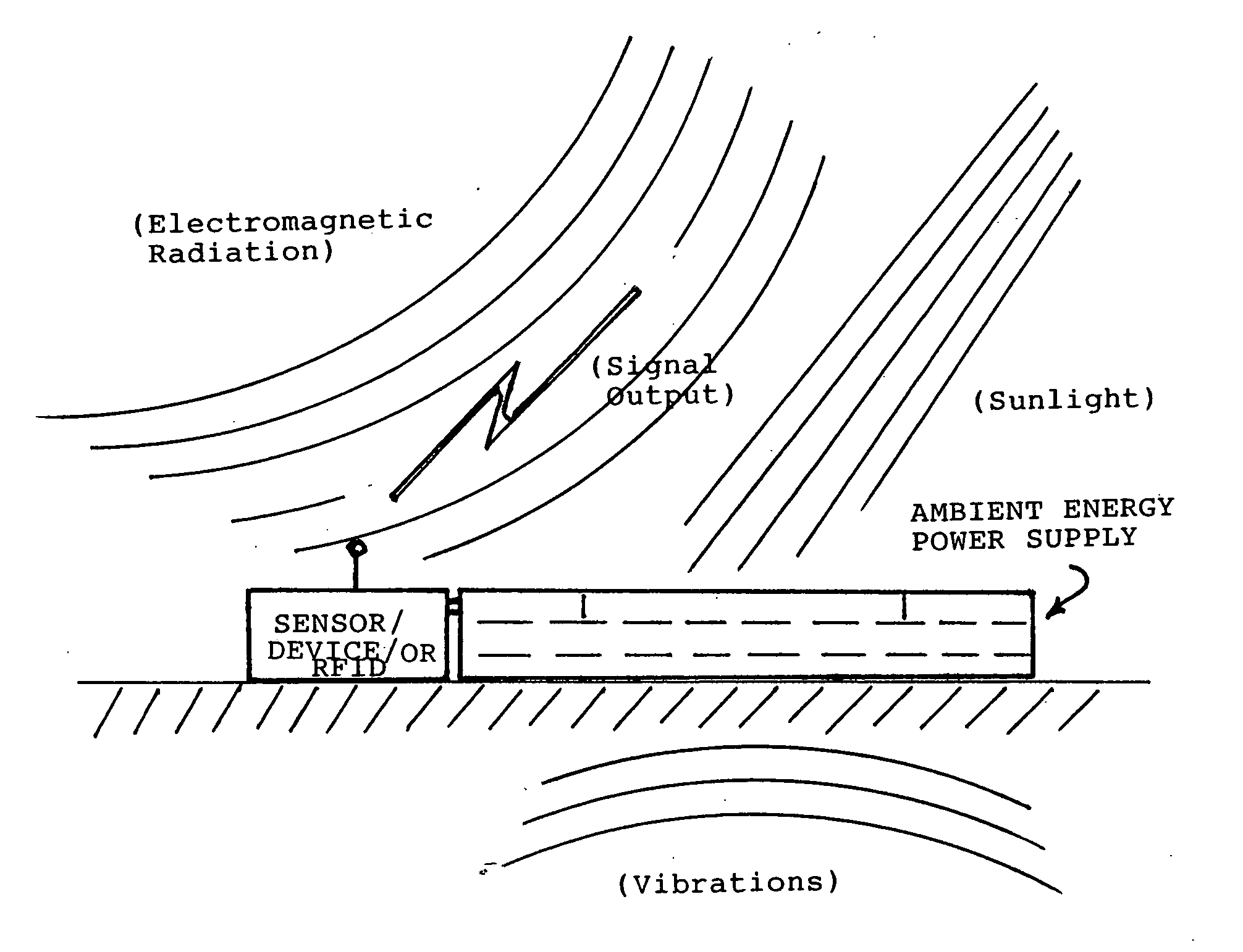
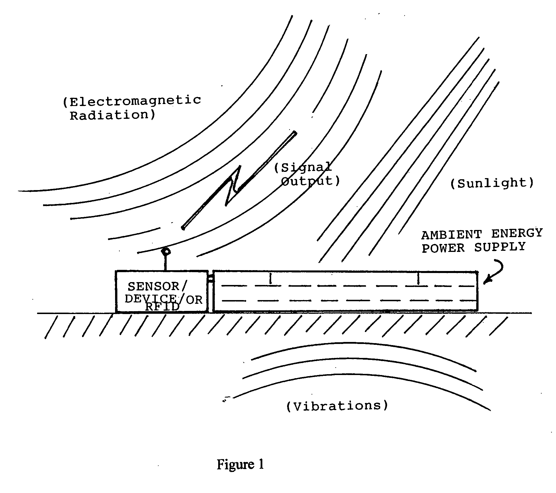
[0020] Referring to FIG. 1, an ambient energy collector and power supply device is shown having at least one ambient energy collector 10 for extracting energy from ambient energy sources in the environment around the device and storing it in an energy storage device 12. Using an output controller, the power supply device can supply power as needed to an associated energy-using device 20. The am...


PUM


Abstract

An ambient electromagnetic energy collector has a magnetic core of high permeability ferromagnetic material wrapped in an inductor coil for coupling primarily to a magnetic field component of a propagating transverse electromagnetic (TEM) wave. For coupling to electromagnetic waves of a wide range of frequencies and magnitudes, the collector is coupled to a multi-phase transformer connected to a multi-phase diode voltage multiplier to provide a current source output to an associated energy storage device. An output controller supplies output power as needed to the associated energy-using device. Preferred types of ferromagnetic materials include nickel-iron alloys with a small percentage of silicon, molybdenum, or copper. It may be combined with other types of ambient energy collectors, such as acoustic / vibration, thermoelectric, and photovoltaic collectors, in a multi-source device provided with a collector interface for converting the different outputs for storage in a common energy storage device. The multi-source ambient energy collector device can be used to supply power to embedded devices, remotely deployed wireless sensors or RFID tags, and other types of monitoring devices distributed over large areas or in industrial environments.

Description

TECHNICAL FIELD [0001] This invention generally relates to a device or system for collecting energy from ambient energy sources and providing it as a power supply for embedded devices or remote sensor or RFID networks. BACKGROUND OF INVENTION [0002] Wireless sensor devices and active RFID tags are limited by the operating life, size, costs, and toxicity of their chemical battery power systems. For embedded and remotely distributed applications, the replacement or recharging of sensor and RFID batteries is impractical and costly. As military and commercial operations increasingly incorporate the use of embedded sensors and remotely distributed wireless devices for “pervasive computing” and “persistent surveillance” applications, there is the corresponding requirement for an alternative, long-lasting power supply that is self-sustaining, reliable and maintenance-free over multiple years of operations in harsh conditions. [0003] For applications that require the mass deployment of disp...

Claims


Application Information

Patent Timeline
IPC IPC(8): H02K7/18H02J7/00H02N6/00
CPCH01F17/045H02S99/00H02K7/18H02J17/00Y02E10/50H02J50/10H02J50/001Y02P80/20
Inventor LANGLEY, JOHN B. IILIAW, BOY YANNWEEKER, SCOTT A.
Owner LANGLEY JOHN B II
Learn More