
Scintillator plate for radiation and production method of the same

a technology of scintillator plate and radiation, which is applied in the direction of optical radiation measurement, fluorescence/phosphorescence, instruments, etc., can solve the problems of insufficient visibility nor spatial resolution, inconvenient image processing of analog data, and insufficient stimulable phosphor plate. , to achieve the effect of higher emission efficiency

Inactive Publication Date: 2007-05-17
KONICA MINOLTA MEDICAL & GRAPHICS INC
View PDF10 Cites 32 Cited by
  • Summary
  • Abstract
  • Description
  • Claims
  • Application Information

AI Technical Summary

Benefits of technology

[0018] An object of the present invention is to provide a scintillator plate for radiation which enables to exhibit a higher emission efficiency and to provide a production method thereof.
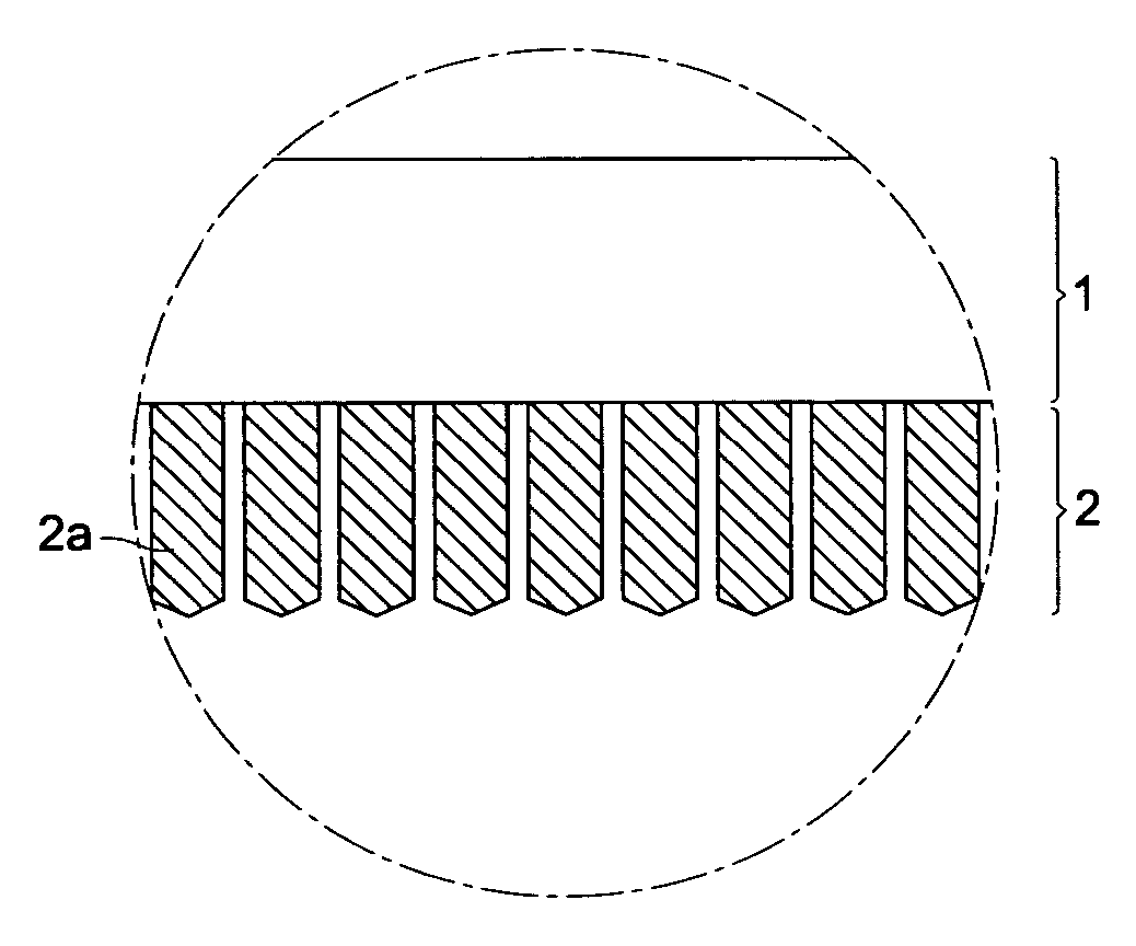
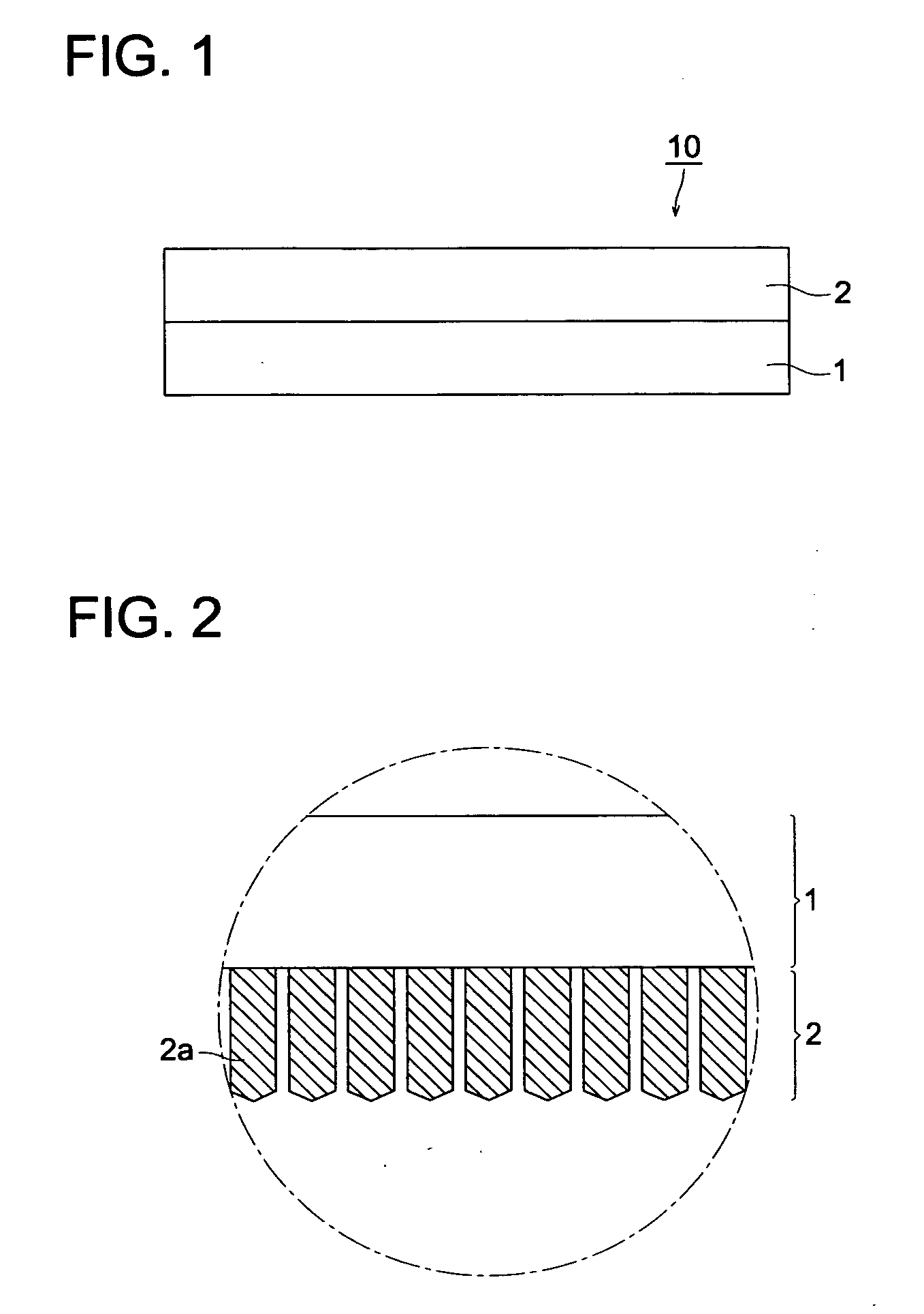
[0019] One of the aspects of the present invention to attain the above object is a scintillator plate for radiation comprising a substrate having thereon a phosphor layer comprising CsI and two or more activators each having a melting point different from a melting point of CsI, wherein each content of the two or more activators is 0.01 mol % or more based on CsI; and the scintillator plate is produced by forming the phosphor layer on the substrate via a vacuum evaporation method using a source material comprising CsI and the two or more activators.
[0020] Another aspect of the present invention to attain the above object is a method to produce a scintillator plate for radiation comprising the steps of: (i) heating a mixture comprising CsI and an activator at 350-620° C. for one hour or more; and (ii) vacuum evaporating the mixture onto a substrate to form a phosphor layer after step (i).

Problems solved by technology

However, obtained in this system are analog data which are not suitable for easy image processing nor quick image transfer.
However, the stimulable phosphor plate has not been fully satisfactory in providing an enough S / N ratio (Signal to Noise ratio), an enough visibility nor an enough spatial resolution of the image and the image quality has not been as high as that of the intensifying screen-film system.
However, the same as in the CR system, the image quality of FPD has not fully been as high as that of the intensifying screen-film system and further improvement has been desired.
In FPD, utilized is a scintillator plate having an X-ray sensitive phosphor to convert the radiation to visible rays, however, the S / N ratio of the scintillator has not fully been large enough due to a considerably large electric noise generated from the TFTs or from the electric circuits to drive the TFTs, when the dose of radiation is low, resulting in failing to provide an enough emitting efficiency to attain high quality images.
However, even when the techniques as disclosed in Patent Documents 1 and 2 are used to prepare an X-ray sensitive phosphor, the emission efficiency when irradiated with X-rays have not fully been high enough.

Method used


Image

  • Scintillator plate for radiation and production method of the same
  • Scintillator plate for radiation and production method of the same
  • Scintillator plate for radiation and production method of the same

Examples


example 1

(Preparation of Evaporation Source Material)

[0127] As the raw materials of a plurality of activators, 0.3 mol % of thallium iodide (TlI) and 0.2 mol % of europium iodide (EuI2) based on CsI were mixed with CsI, pulverized and homogenized in a mortar.

(Preparation of Radiation Image Conversion Panel)

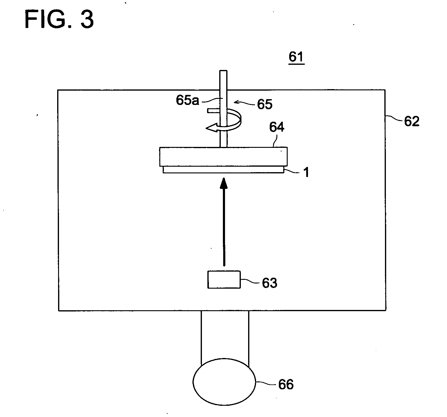
[0128] On one surface of a substrate containing a carbon fiber-reinforced resin sheet, the above evaporation source material was vacuum evaporated using the vacuum evaporation apparatus 61 to form a phosphor layer. Namely, at first, the above evaporation source material was loaded in a resistance heating boat 63, then, the substrate 1 was fixed in a substrate holder which was rotated by the rotation mechanism 65, and the distance between the substrate 1 and the resistance heating boat 63 was adjusted to 400 mm. The inside of the vacuum evaporation apparatus 62 was once evacuated and Ar gas was introduced to adjust the vacuum at 0.1 Pa. The temperature of the substrate 1 was kept at 15...

example 2

[0130] A radiation image conversion panel was prepared in the same manner as the radiation image conversion panel of Example 1 except that 0.2 mol % of TlI, 0.2 mol % of EuI2 and 0.1 mol % of rubidium iodide (RbI) based on CsI were used as the plurality of activators. The obtained radiation image conversion panel was adopted as the radiation image conversion panel of Example 2. The luminance was measured in the same manner as in Example 1 and was found to be 3.1. The result was listed in Table 1.

example 3

[0131] A radiation image conversion panel was prepared in the same manner as the radiation image conversion panel of Example 1 except that 0.2 mol % of T1I, 0.2 mol % of EuI2 and 0.1 mol % of copper iodide (CuI) based on CsI were used as the plurality of activators. The obtained radiation image conversion panel was adopted as the radiation image conversion panel of Example 3. The luminance was measured in the same manner as in Example 1 and was found to be 2.5. The result was listed in Table 1.


PUM


Abstract

A scintillator plate for radiation comprising a substrate having thereon a phosphor layer comprising CsI and two or more activators ach having a melting point different from a melting point of CsI, wherein each content of the two or more activators is 0.01% or more based on CsI; and the scintillator plate is produced by forming the phosphor layer on the substrate via a vacum evaporation method using a source material comprising CsI and two or more activators.

Description

[0001] This application is based on Japanese Patent Applications No. 2005-331639 filled on Nov. 16, 2005, and No. 2005-353253 filed on Dec. 7, 2005 Japanese Patent office, the entire content of which is hereby incorporated by reference. FIELD OF THE INVENTION [0002] The present invention relates to a scintillator plate for radiation principally composed of cesium iodide and a production method of the scintillator plate. BACKGROUND OF THE INVENTION [0003] Hitherto, radiation images such as X-ray images have been widely applied for diagnosing in medical field. Particularly, an intensifying screen-film radiation image forming system is still used in the medical field in the world as an image forming system having high reliance and superior cost performance as a result of improvement in sensitivity and image quality in long history of the system. However, obtained in this system are analog data which are not suitable for easy image processing nor quick image transfer. [0004] After that,...

Claims


Application Information

Patent Timeline
Patent Type & Authority Applications(United States)
IPC IPC(8): G01J1/58
CPCG01T1/202C09K11/616C09K11/628C09K11/7705C09K11/7733G21K4/00G21K2004/06G21K2004/12
Inventor SHOJI, TAKEHIKONAKANO, YASUSHISAKAI, MIKA
Owner KONICA MINOLTA MEDICAL & GRAPHICS INC
Learn More