

Injection molding fabrication method
a fabrication method and injection molding technology, applied in the field of injection molding fabrication methods, can solve the problems of inherently limiting the performance and range of applications of rotary tools, drills and other rotary tools having a monolithic construction, and not experiencing uniform wear and/or chipping and cracking of the cutting edges of the tool, and relatively short service life of such drills
- Summary
- Abstract
- Description
- Claims
- Application Information
AI Technical Summary
Benefits of technology
Problems solved by technology
Method used
Image

Examples
Embodiment Construction
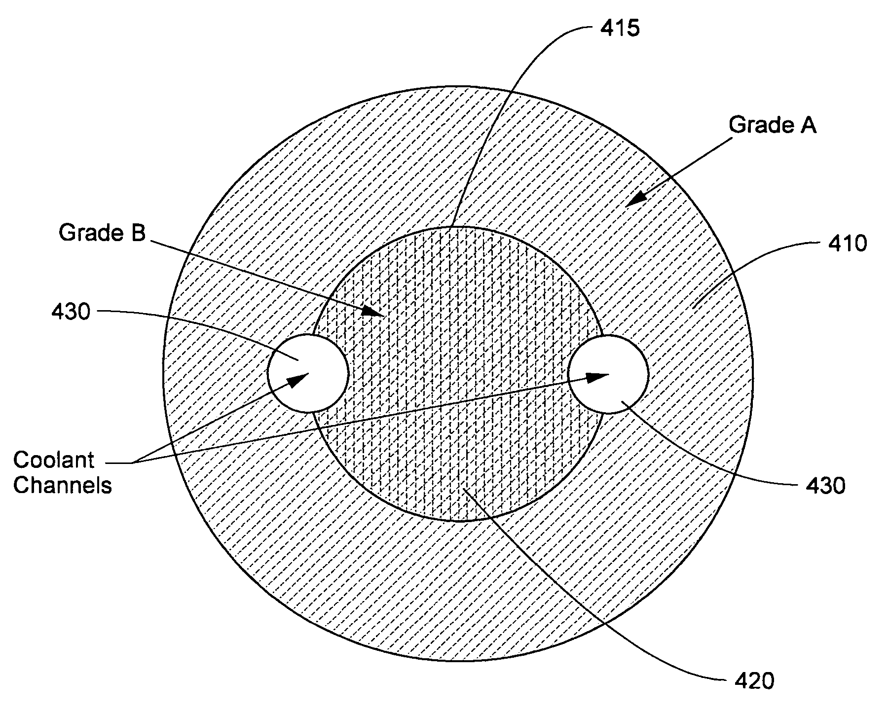
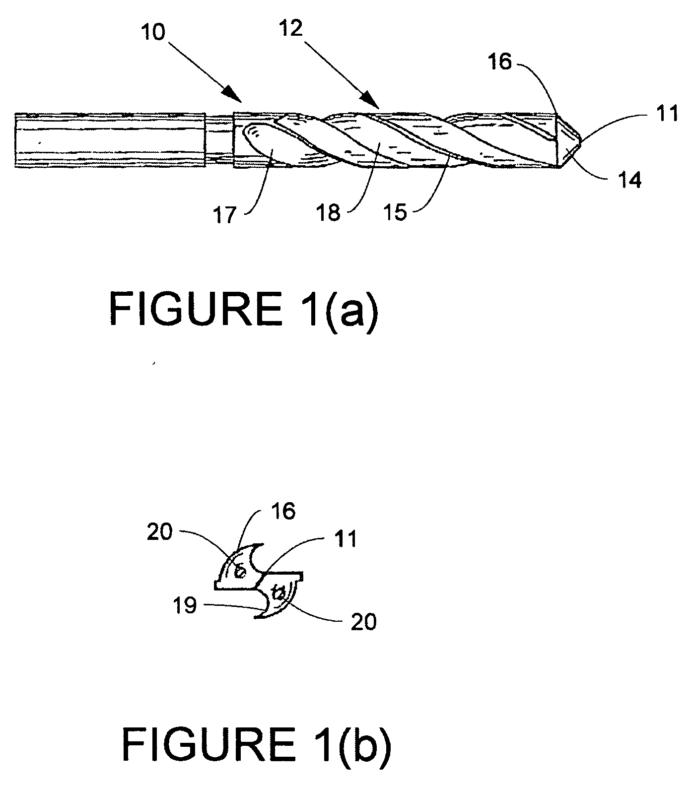
[0023] The present invention provides rotary cutting tools, cutting tool blanks, rods, and other articles having a composite construction and a method of making such articles. The articles may further comprise internal channels, such as coolant channels, if desired. As used herein, a rotary tool is a tool having at least one cutting edge that is driven to rotate. As used herein, “composite” construction refers to an article having regions differing in chemical composition and / or microstructure. These differences result in the regions having properties differing with respect to at least one characteristic. The characteristic may be at least one of, for example, hardness, tensile strength, wear resistance, fracture toughness, modulus of elasticity, corrosion resistance, coefficient of thermal expansion, and coefficient of thermal conductivity. Composite rotary tools that may be constructed as provided in the present invention include drills and end mills, as well as other tools that m...
PUM
| Property | Measurement | Unit |
|---|---|---|
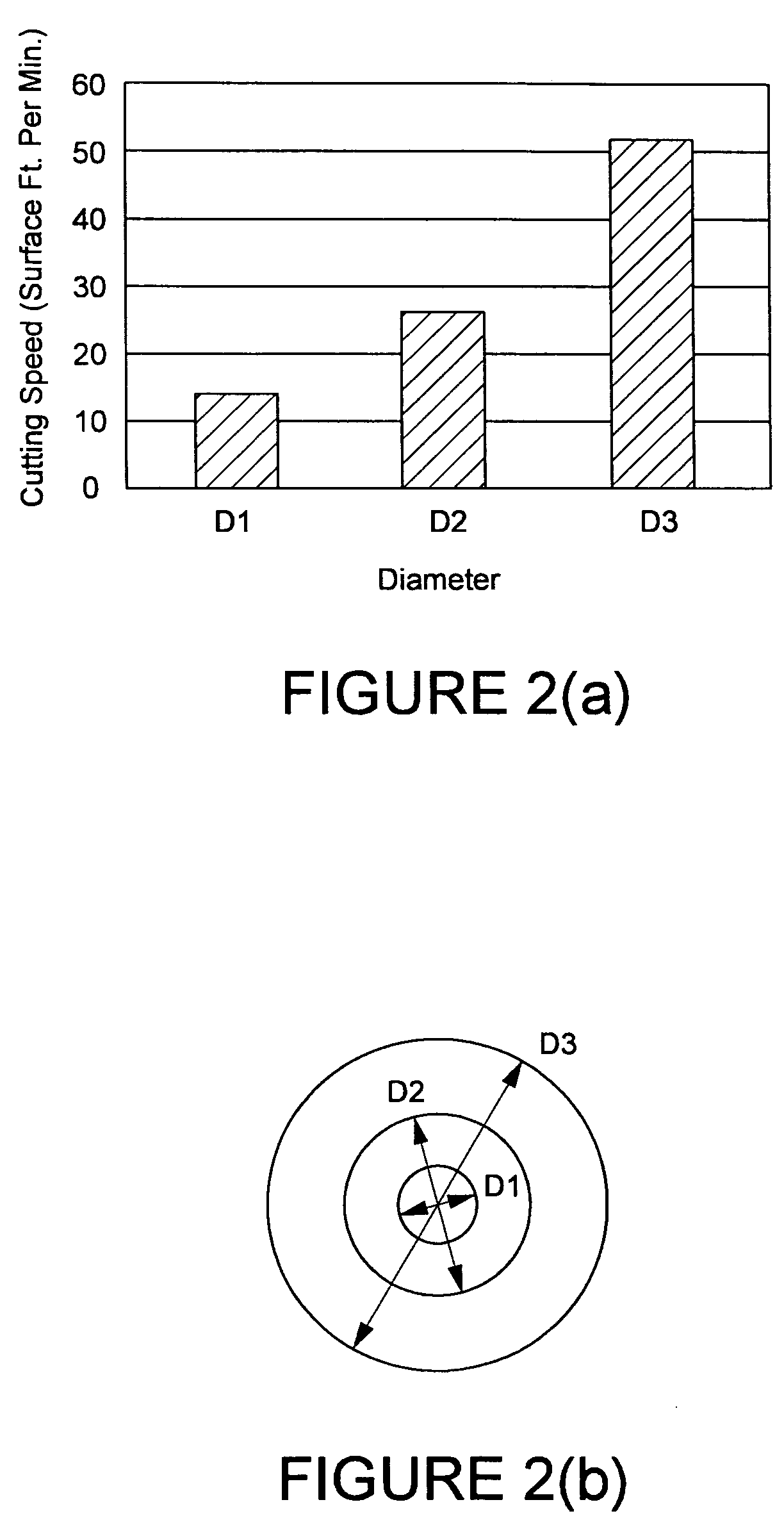
| diameters D1 | aaaaa | aaaaa |
| diameters D1 | aaaaa | aaaaa |
| diameters D1 | aaaaa | aaaaa |
Abstract
Description
Claims
Application Information