
Resonant gate drive circuit with centre-tapped transformer

Inactive Publication Date: 2007-05-17
GANPOWER SEMICON FOSHAN LTD
View PDF11 Cites 18 Cited by
  • Summary
  • Abstract
  • Description
  • Claims
  • Application Information

AI Technical Summary

Benefits of technology

[0018] Clamping the gate capacitance of the power switching device to a low voltage may comprise clamping the gate capacitance approximately to ground of the circuit. In another embodiment, clamping the gate capacitance of the power switching device to a low voltage may comprise clamping the gate capacitance to a voltage that is equal to or less than that required to maintain the power switching devi

Problems solved by technology

An increase in gate drive loss is one drawback, since it is a frequency-related loss.
Thus, a higher switching frequency will result in increased power dissipation, which may cause the gate driver to be destroyed by overheating.
Also, the gate loss takes a considerable share in total power dissipation, which reduces the efficiency of the converter significantly.
Moreover, the conventional gate driver cannot meet the switching speed requirement of high frequency applications.
Consequently, a longer turn-off transition occurs, which does not help to reduce switching loss and conduction loss.
However, this results in increased component cost.
However, such attempts are unsatisfactory or require gate control signals that are difficult to generate.

Method used


Image

  • Resonant gate drive circuit with centre-tapped transformer
  • Resonant gate drive circuit with centre-tapped transformer
  • Resonant gate drive circuit with centre-tapped transformer

Examples


example 1

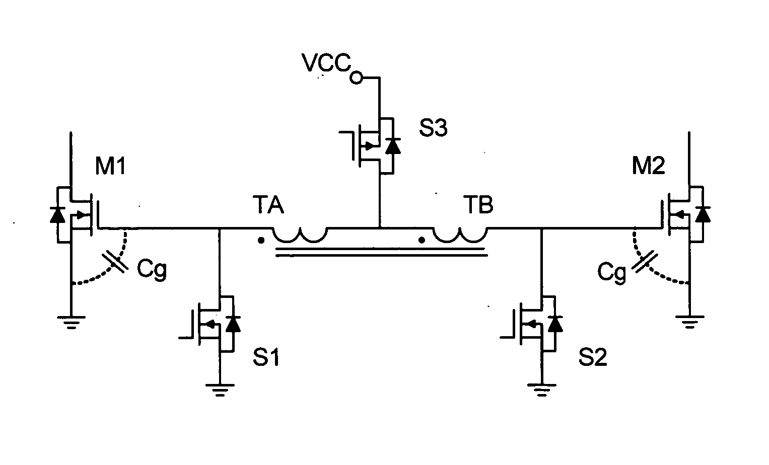
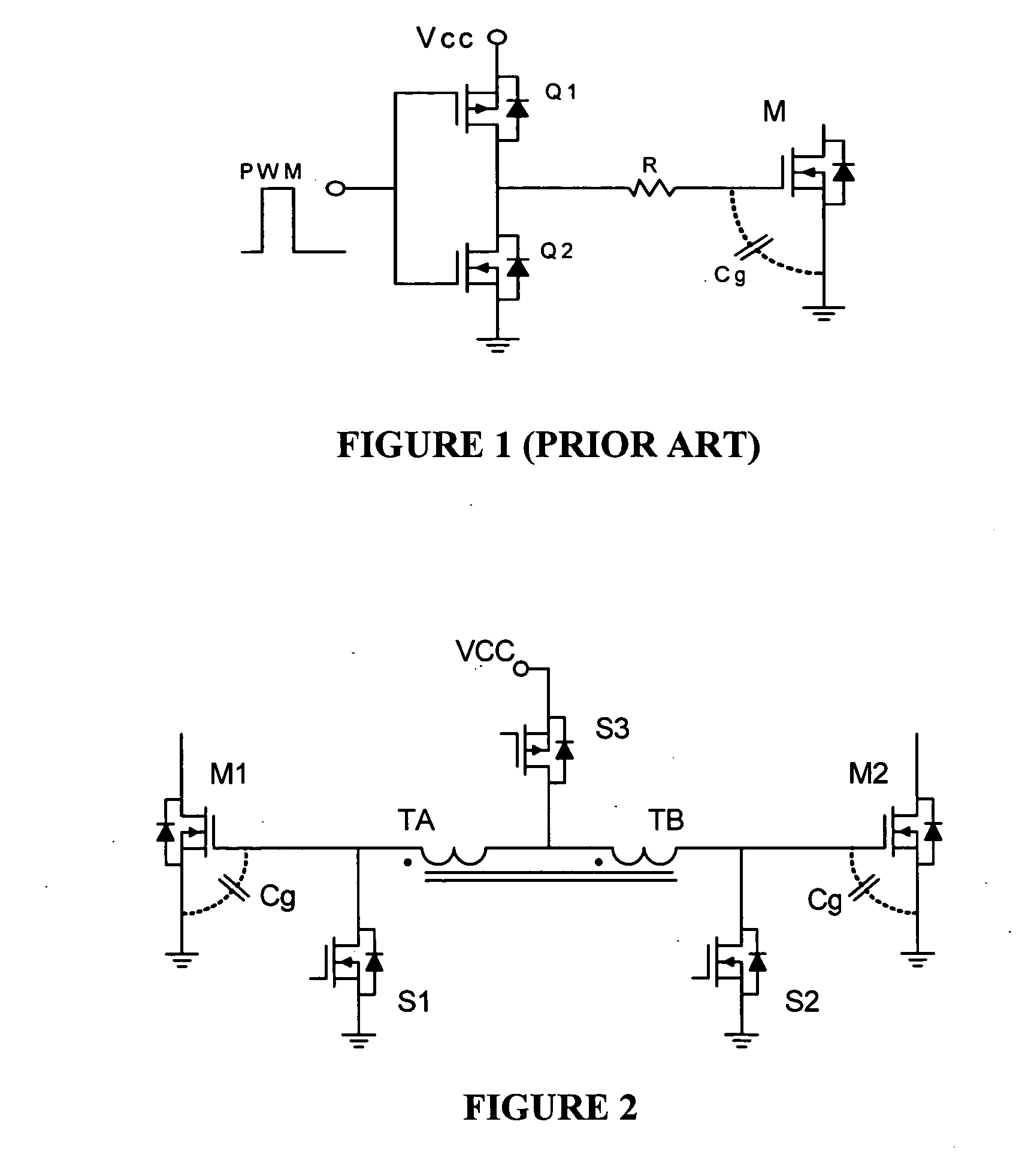
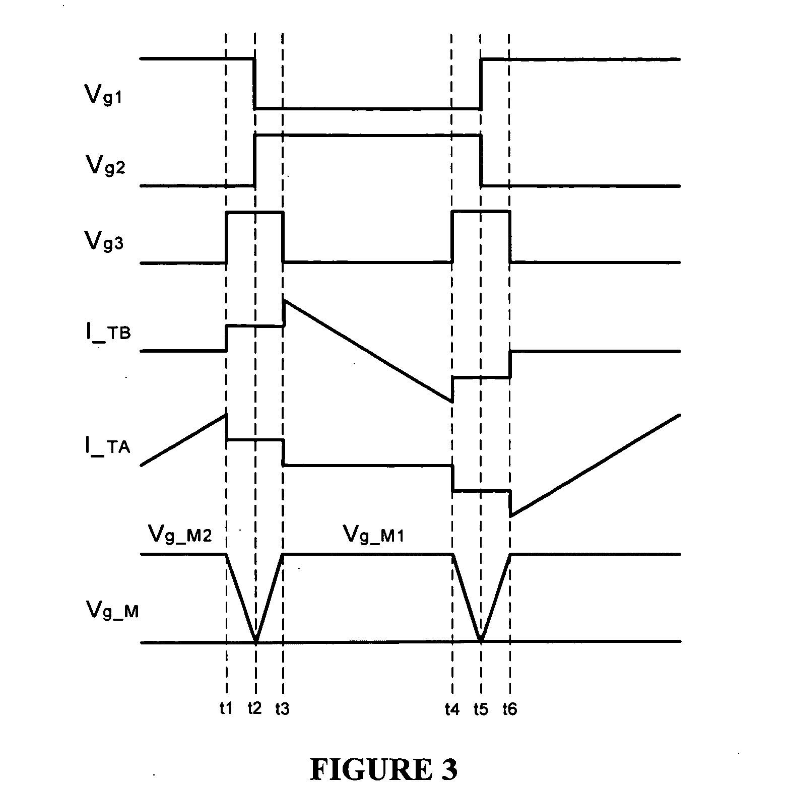
[0072] A computer simulation was done to evaluate the resonant gate driver circuit of FIG. 2. The simulation results at switching frequencies of 1 MHz and 2 MHz are shown in FIGS. 7 and 8, respectively. The simulation conditions were as follows:

[0073] The supply voltage Vcc was 5 V. Switching frequencies were set at 1 MHz and 2 MHz, and corresponding magnetizing inductances were 900 nH and 250 nH, respectively. A 3.9 nF capacitor was used to simulate the gate capacitance of the power MOSFET. It was assumed that there was no leakage inductance.

[0074] A prototype of the resonant gate driver circuit was built. The voltage of the power supply was 5 V and the clock frequency was set at 1 MHz. All logic circuitry was implemented using discrete gate components. FIG. 6 shows the logic circuit for the driver. A toroid core transformer (Micrometals T44-15) was used for the centre-tapped transformer, in which a bifilar wire winding construction was employed to minimize leakage inductance. Th...

example 2

[0080] A computer simulation was performed on the resonant gate drive circuit of FIG. 12. The simulation conditions included: source voltage Vcc was 5 V, switching frequency was 1 MHz, magnetizing inductances were 800 nH. A 5 nF capacitor was used to simulate the equivalent gate capacitance of the MOSFETs. The simulation assumed no leakage inductance. Simulation results are shown in FIG. 14, wherein it can be seen that the simulated circuit performed as expected.

[0081] In addition, an experimental circuit was built based on a 50% duty cycle Buck converter. The input voltage was 10 V and the supply voltage Vcc was 5 V. The clock frequency was 1 MHz. The logic control circuit was built using discrete gate components. A toroid core transformer (T44-15) from Micrometals was used for the centre-tapped transformer in which a bifilar wire winding construction was employed to minimize the leakage inductance of transformer. The magnetizing inductance was 800 nH. The turns ratio was 1:1:1.2,...


PUM


Abstract

This invention relates to a resonant gate drive circuit for a power switching device, such as a MOSFET, that uses a centre-tapped transformer to increase the driving gate voltage approximately twice as high as the supply voltage. The gate capacitance of the power switching device is charged and discharged by a constant current source, which increases the switching transition speed of the power switch. The circuit is suitable for driving a pair of low side switches with 50% duty cycle or less, such as in a variable frequency resonant converter, push-pull converter, or the like.

Description

RELATED APPLICATIONS [0001] This application claims the benefit of the filing date of U.S. Provisional Patent Application No. 60 / 733,213, filed on Nov. 4, 2005, the contents of which are incorporated herein by reference in their entirety.FIELD OF THE INVENTION [0002] This invention relates to a resonant gate drive circuit for driving a power switching device, such as a power switch in a power converter. In particular, the invention relates to a resonant gate drive circuit that provides a high gate voltage to drive a power switching device. BACKGROUND OF THE INVENTION [0003] As development of computing and telecom technologies continues, high power density is increasingly required in switching power supply design. There is a trend toward increasing the switching frequency, and it will soon be in the megahertz range. Along with the benefits of higher operating switching frequency, such as compact size and faster loop response, there are also several drawbacks. An increase in gate driv...

Claims


Application Information

Patent Timeline
IPC IPC(8): H03K5/22H03K17/72
CPCH03K17/04123H03K17/693H03K2217/0036
Inventor LIU, YAN-FEIXU, KAI
Owner GANPOWER SEMICON FOSHAN LTD
Learn More