
Methods for the management of erase operations in non-volatile memories

a technology of non-volatile memory and management method, which is applied in the direction of memory architecture accessing/allocation, instruments, computing, etc., to achieve the effect of improving the erase process and reducing the execution tim

Inactive Publication Date: 2007-05-17
SANDISK TECH LLC
View PDF15 Cites 44 Cited by
  • Summary
  • Abstract
  • Description
  • Claims
  • Application Information

AI Technical Summary

Benefits of technology

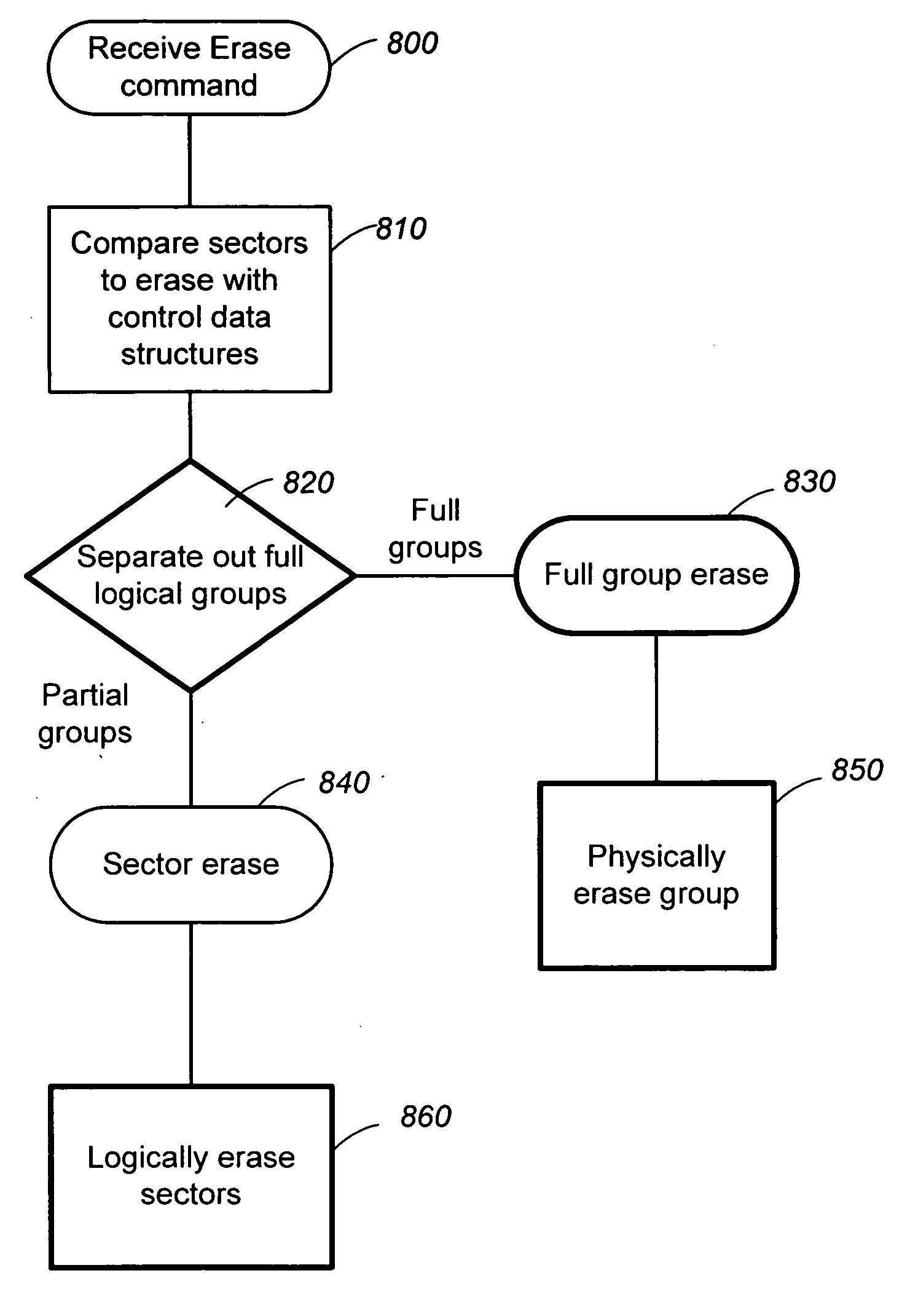
[0016] According to a principle aspect, the present invention improves the erase process by splitting erase commands into portions corresponding to a full logical group (a group of contiguous sectors usually the same size as a meta-block or other logical grouping of erase blocks), which can then be physically erased or otherwise subjected as a whole to an erase operation, and portions corresponding to only part of a logical group (such as individual sectors), which are logically erased by, for example, writing a pattern corresponding to an erased state or setting an indication in the sectors header. When a host issues an Erase Sectors command, the memory system uses its control data structures, by with the controller organizes the erase blocks of the memory into logical units, to determine which, if any, of the specified sectors span a full logical group. When a full logical group to be erased, the memory can execute the command by the means of physical block erases rather than by writing the erased sector pattern to all sectors. By doing this, the execution time can be made much shorter, especially in the case when the entire card is erased by a single command. According to another aspect, the invention solves problems that may arise due to power loss recovery. This may occur as a block, which was being erased when power was lost, may look corrupted or the either erased or well programmed, but may be disturbed by the previously aborted erase operation. In a further aspect, the invention is able is to provide compatibility with the protocols where the system needs to return the information about whether the sector being read was erased by an Erase Sectors command or not. In another aspect of the present invention, an “erased block” )or “erased sector”) status can be returned if a sector belonging to the block (or the sector itself) is erased.

Problems solved by technology

This may occur as a block, which was being erased when power was lost, may look corrupted or the either erased or well programmed, but may be disturbed by the previously aborted erase operation.

Method used


Image

  • Methods for the management of erase operations in non-volatile memories
  • Methods for the management of erase operations in non-volatile memories
  • Methods for the management of erase operations in non-volatile memories

Examples


first embodiment

[0142] In a first embodiment, when the sectors to be erased span a logical group, the corresponding metablocks are physically erased and the erased group or groups are added to the existing erase pool. This can be implemented by introducing a set of firmware that can support the physical erase of logical groups and an increase in the erase pool. The main focus of the method is to provide a safe sequence of erase operations and control updates, so that the card can be recovered in the case of power loss.

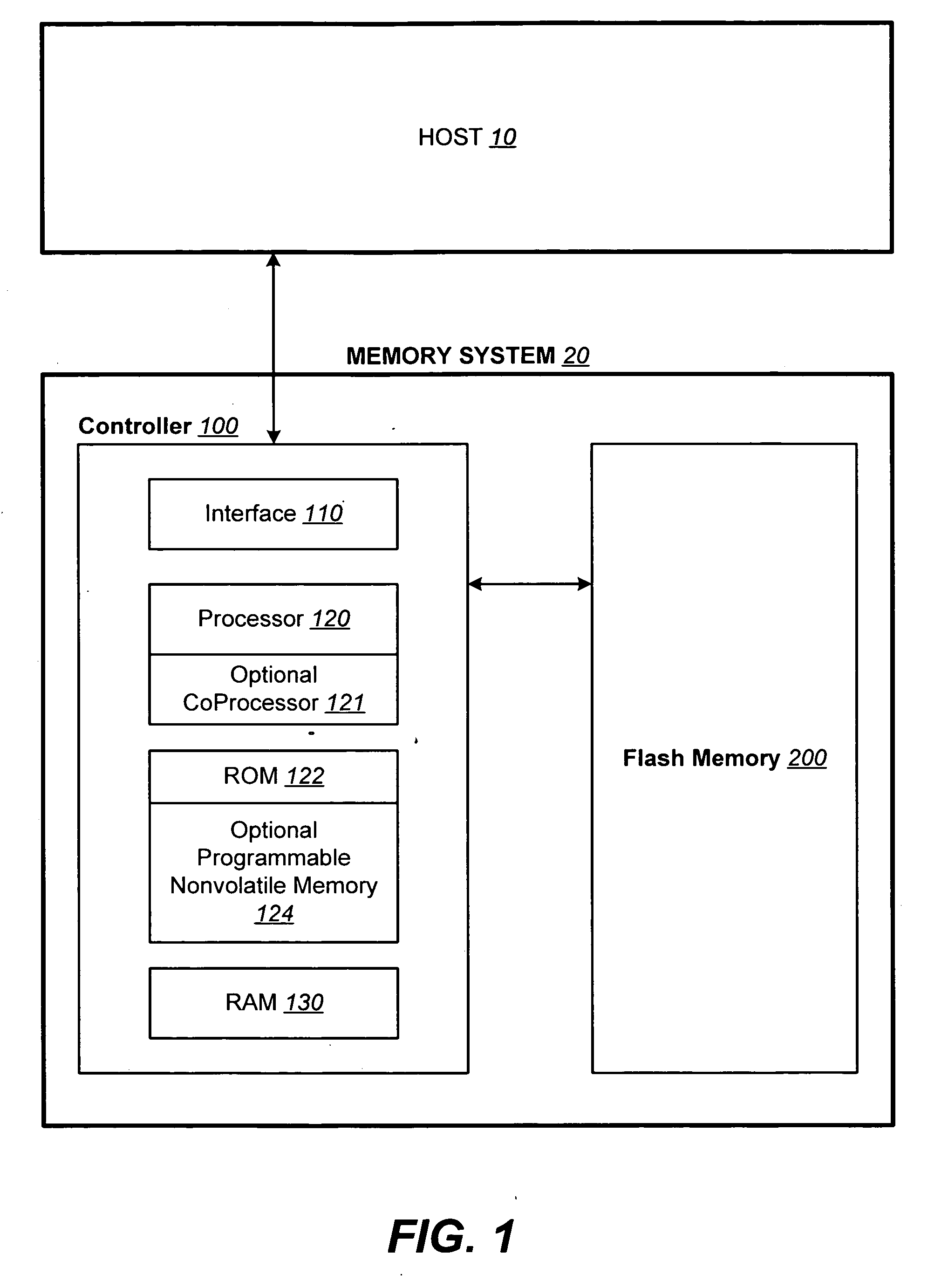
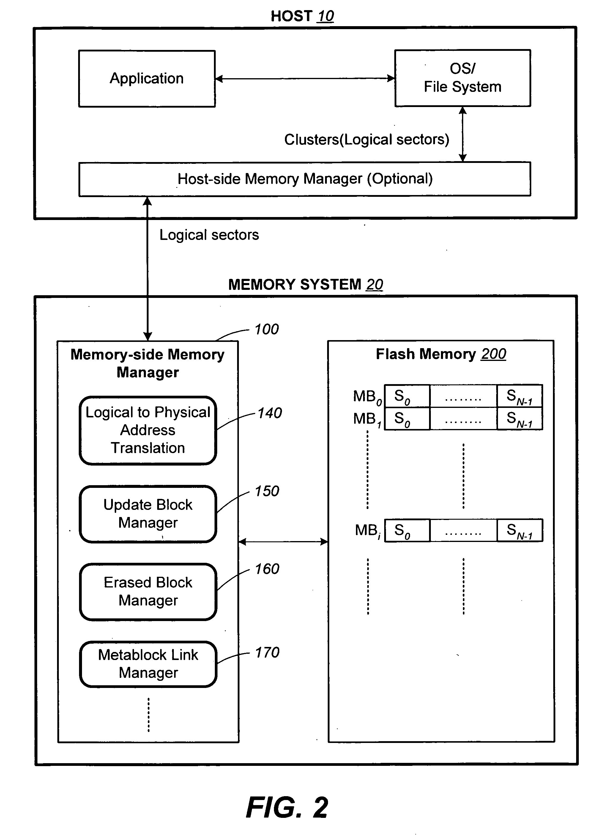
[0143] The controller 100 (FIG. 1) of the memory system 20 will typically have its hardware, firmware, software, or some combination of these split into a front end (FE) and back end (BE), where the front end is the front or host interface memory system. The back end will then be a media management part that can be common for differing interfaces and across different products. In the exemplary memory system, a main part of the back end is a media management layer (MML) that makes the ...

third embodiment

[0163] A third embodiment is just to reformat the memory in case of a format command (which means Erase Sectors for the entire card), so that the card is reformatted as new. In order to do this, the memory system should contain the formatted code, where it is preferable that the formatter code is able to determine new, grown bad blocks. Although this results in card pre-conditioning, it may require extra memory space and a more advanced formatter.

(iv) Block Erase Without Updates

[0164] In another embodiment, the system will erase metablocks for the “erased” logical groups, but without updating the erased block lists (EBL) 230 and MAP 240. Under this approach, the metablock to which the GAT points is erased. The system should make sure that the logical group to be “erased” is consolidated into an intact metablock and the GAT is updated to point to the erased metablock, so that it does not get lost. The erased block lists (EBL) 230 and MAP 240 should be updated as if the metablock is...

fifth embodiment

[0165] A fifth embodiment uses a fast true erase done by single blocks. The information of a requested erase is recorded in erase block management (EBM, 760) sector, then the meta-block pointed by the GAT will be erased. The GAT can then be updated with the null pointer and the erased block can be added to the erased block lists (EBL) 230 and MAP 240.

[0166] This method would introduce a new set of firmware functions that can support the physical erase of logical groups and their addition to the erase pool. The main focus of the method is to provide a safe sequence of erase operations and control updates so that the card can be recovered in the case of power loss. A number of implementations are possible, but the following exemplary sequence executed by the media management layer can provide a safe mechanism for erasing a logical group:

[0167] 1. Ensure that the logical group to be erased is consolidated into an Intact meta-block and the GAT is updated to point to the meta-block, whi...


PUM


Abstract

The present invention presents a number of improvements for managing erase processes in non-volatile memory. Such memory systems typically manage the memory by logically organize the basic unit of physical erase (erase block) into composite logical groupings (meta-blocks or logical group), where an erase block generally consists of a number of sectors. When an erase command is received, the specified sectors are checked against the memory system's control data. If the specified sectors span any full logical grouping, the full logical groupings can each be treated a whole and erased according to one process (such as performing a true, physical erase), while other sectors are “logically” erased at the sector level by standard techniques.

Description

CROSS-REFERENCE TO RELATED APPLICATION [0001] The present application is related to U.S. application Ser. No. ______, of Bennett et al., entitled “Structures for the Management of Erase Operations in Non-Volatile Memories,” which is filed concurrently with the present application and is hereby incorporated herein, in its entirety, by this reference.FIELD OF THE INVENTION [0002] This invention relates generally to non-volatile semiconductor memory and specifically to the management of erase processes in such memories. BACKGROUND OF THE INVENTION [0003] Solid-state memory capable of nonvolatile storage of charge, particularly in the form of EEPROM and flash EEPROM packaged as a small form factor card, has recently become the storage of choice in a variety of mobile and handheld devices, notably information appliances and consumer electronics products. Unlike RAM (random access memory) that is also solid-state memory, flash memory is non-volatile, and retaining its stored data even aft...

Claims


Application Information

Patent Timeline
Patent Type & Authority Applications(United States)
IPC IPC(8): G06F13/00G06F12/00
CPCG06F12/0246G06F2212/7205G11C16/16
Inventor BENNETT, ALAN DAVIDBRYCE, ALAN DOUGLASGOROBETS, SERGEY ANATOLIEVICH
Owner SANDISK TECH LLC
Learn More