Dual-plasma-fusion jet thrusters using DC turbo-contacting generator as its electrical power source

a technology of turbo-contacting generator and dual-plasma fusion jet, which is applied in the direction of machines/engines, marine propulsion, vessel construction, etc., can solve the problems of less efficiency and more physical space, and achieve the effects of less propellant, higher power density, and less propellan

Inactive Publication Date: 2007-05-24
DAW SHIEN SCI RES & DEV
View PDF13 Cites 2 Cited by
  • Summary
  • Abstract
  • Description
  • Claims
  • Application Information

AI Technical Summary

Benefits of technology

[0021] An advantage of the present invention is that a higher thrust and higher power density of dual-plasma can be achieved, and therefore less propellant and less physical space being needed.
[0023] Yet another advantage of the present invention is the inclusion of an electric start system for providing a “warm-up” process for this unit. Before this unit is self-sustaining in replenishing the fuel, oxygen, and humidity, battery's power is provided to rotate dual-outer-contacting surfaces and rollers generating electricity, which is using for electrifying plasmas and then those plasmas running through nozzles increasing the current of plasmas into a “C” shaped electromagnet opening space.
[0024] Yet another advantage of the present DC contacting generator invention is with the dual-most-outer moving surfaces rotating oppositely, which are led by turbines. Those dual-outer surfaces can have the most contacting surface area and fast velocities to generate high-power DC electricity by contacting rollers in-between those dual-outer surfaces as the modified contacting method to the Van de Graaff contacting generator. Therefore, the present invention is a reliable high-power device.
[0025] Yet another advantage of the present invention is the high power density of dual-plasma generated by this high-power DC turbo-contacting generator having lighter weight in comparison to the traditional high-power DC generator, thereby its increasing power and lighter weight make it easy to fly up with enhancing efficiency of using less propellant.
[0026] Yet another advantage of the present invention is the higher operation temperature range (2,200° C.-2,700° C.) at which the dual-plasma flying object's turbines operate, thereby generating the higher power of DC electricity by contacting two oppositely-rotated surfaces with different material-made rollers in-between, and further with no heavy armature or stator of the conventional electromagnetic DC generators.
[0028] Electrical power is needed for starting this [GerTh-DawShien. V] flying object's (Thruster V) two-outer contacting surfaces with rollers in-between to rotating by batteries, and the contacting surfaces will generate high-power DC after the dual-contacting surface reaching to their steady-states, then the next cycle's fuel supplies are electrified and transformed them from molecular forms into ionizing forms. The electrifying plasma streams are squeezed out fast from ionizing chamber nozzles, plasmas attracting toward each other, and ejected out from opposite sides into the latitudinal opening of the “C” shaped magnet generating the action plasmas bent-down force and the reaction lifting thrust. And then, combustion and neutralization are conducted also with the action force direction according to the right hand rule and enhancing guided linear reaction motion. The exhaustion stream sustains its turbines power demands for the next electricity generation cycle by leading two-outer contacting surfaces rotating-oppositely in stable ways.

Problems solved by technology

In recent years, the conventional single plasma thrusters have generated some current density with a jerky motion which results in less efficiency and requires more physical space.

Method used


Image

  • Dual-plasma-fusion jet thrusters using DC turbo-contacting generator as its electrical power source
  • Dual-plasma-fusion jet thrusters using DC turbo-contacting generator as its electrical power source
  • Dual-plasma-fusion jet thrusters using DC turbo-contacting generator as its electrical power source

Examples


Embodiment Construction

[0029] The advantages and the present invention will become better understood with referencing to the following more detailed descriptions and claims taken in conjunction with the accompanying drawings, in which like elements are identified with like symbols, and in which:

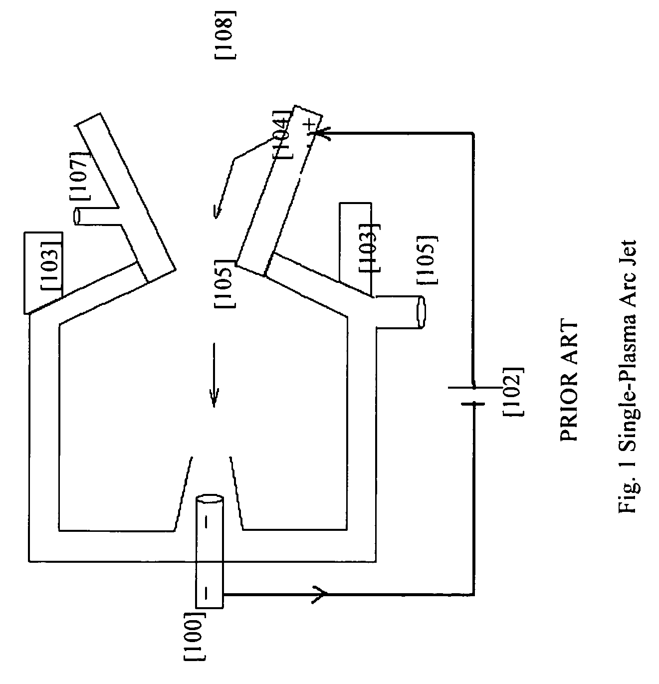
[0030]FIG. 1, is a schematic diagram of a conventional single (one) plasma arc jet according to the PRIOR ART;

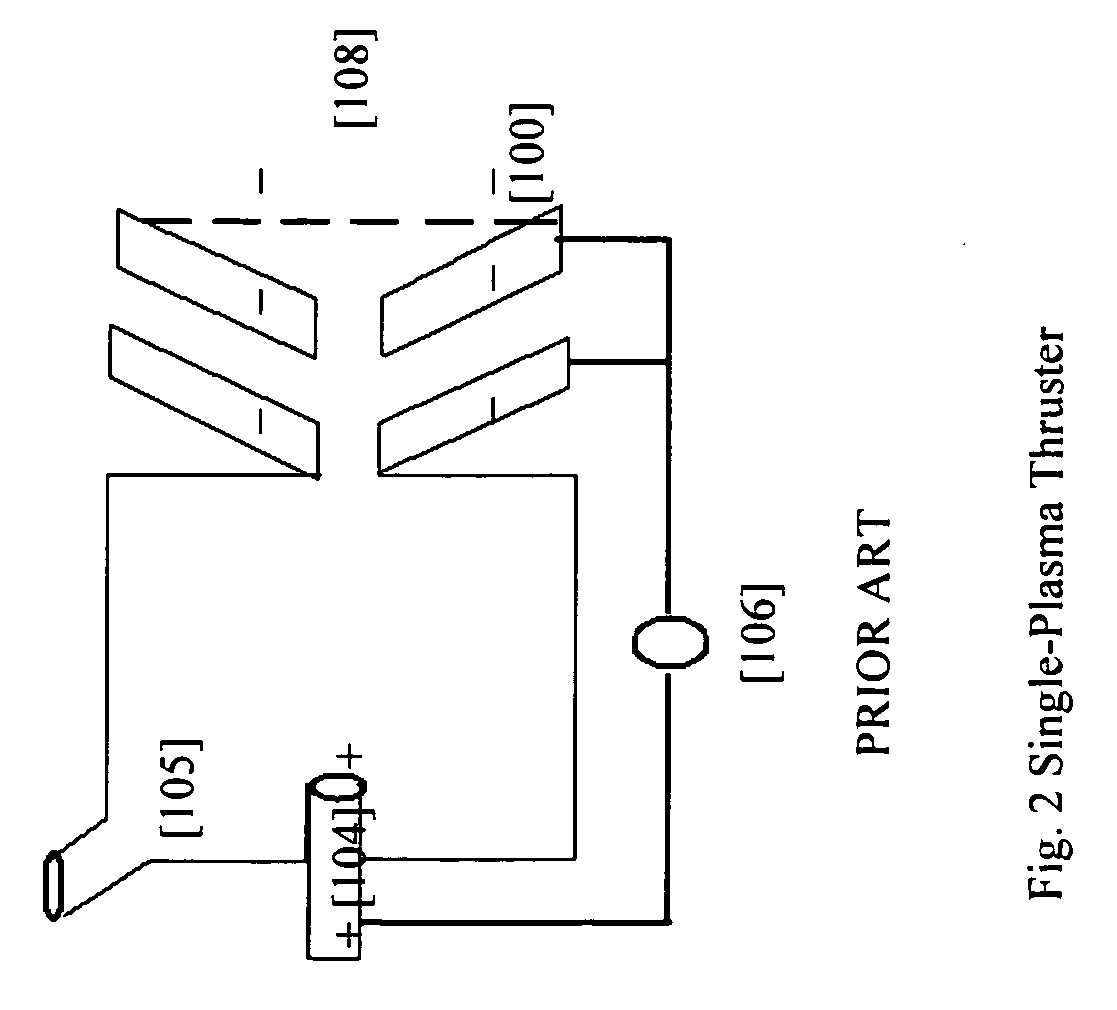
[0031]FIG. 2, is a schematic diagram of a conventional single (one) plasma thruster according to the PRIOR ART;

[0032]FIG. 3, Is a schematic illustration of the slowing abrupt (jerky) motion of a boy standing on the skating board and playing electrical balls with throwing-catching-missing games between his hands;

[0033]FIG. 4, is a schematic illustration of the nozzles jetting the dual-plasma out from both sides increasing their electric current amount in useful ways;

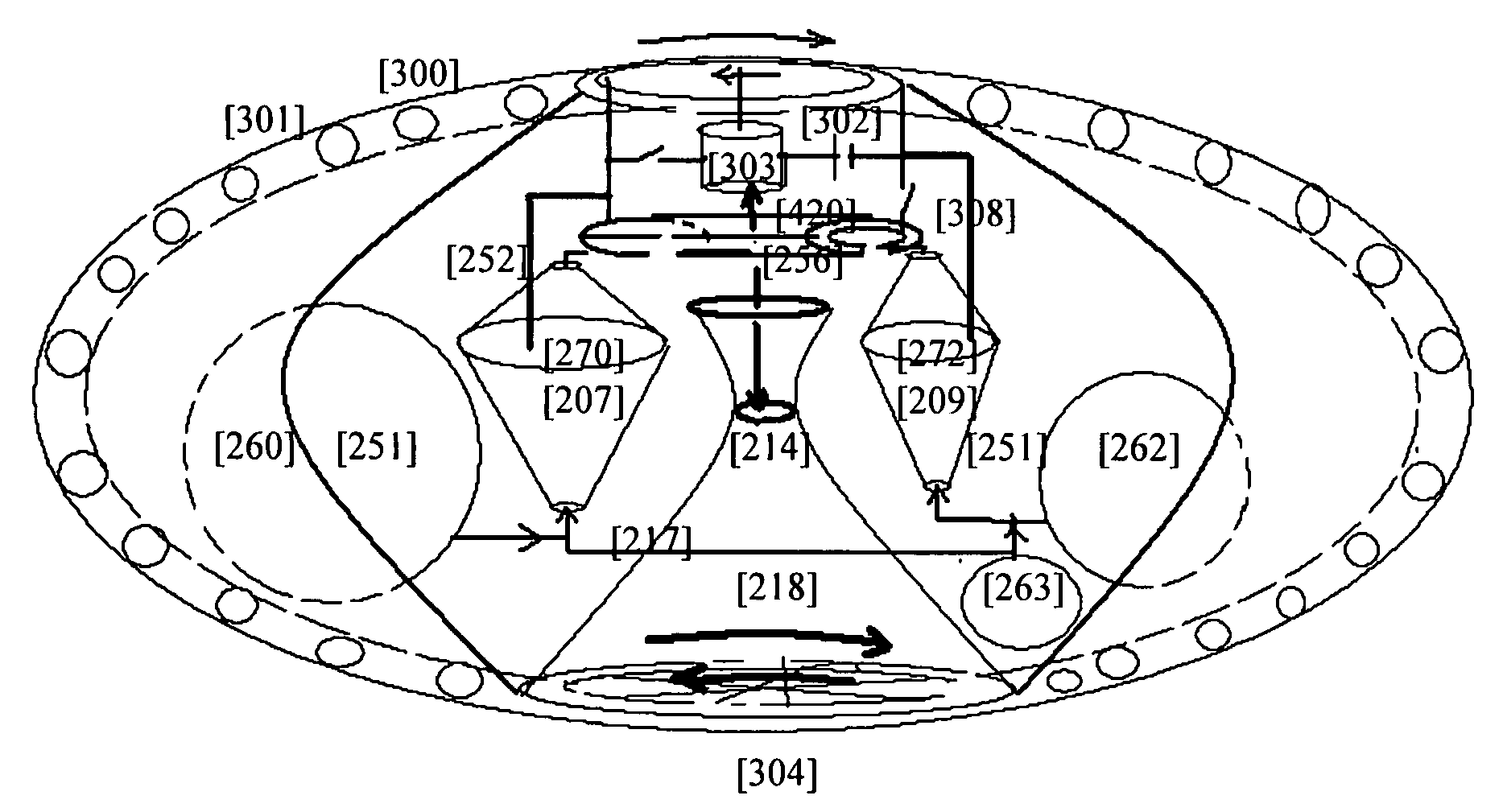
[0034]FIG. 5, is a schematic diagram of the Fifth [GerTh-DawShien. V] dual-plasma flying object (referred to as [Thruster V]) including an ...


PUM


Abstract

New [GerTh-DawShien. V] dual-plasma flying object and [GerTh-DawShien. VI] dual-plasma-fusion flying object provide the electric start system to start their warm-up process to their steady-states, automatically. After their warm-up processes done and the operation conditions reached, the [Thruster V]& [Thruster VI] will run themselves, independently by continuously supplying fuel, oxygen, and moisture into the units. Their electrical power will be generated from the [ShihHwa. V] DC turbo-contacting generator by different material-made surfaces and rollers contacting reaction and then, its electricity supplies transform gases from their molecular forms into ionized forms by electrifying reaction. When dual plasmas are fast ejected from nozzles into the ‘C’ shaped magnet's opening, their current will be increasing and plasmas will be bent downward, according to the right hand rule. The linear upward reaction thrust is generated. Thereafter, the plasmas combustion, neutralization, and fusion reactions are conducted also to the action direction and their reaction force for propelling the flying object in the opposite linear guided motion, upward and forward.

Description

RELATED APPLICATIONS [0001] The present invention is a Continuation in Part of U.S. Ser. No. 10 / 929,023 filed on Aug. 30, 2004, which a Continuation in Par was U.S. Ser. No. 10 / 970,152, filed on Oct. 22, 2004, 2004, and both incorporated by reference herein as if fully rewritten.BACKGROUND OF THE INVENTION [0002] 1. Field of the Invention [0003] The present invention relates generally using DC turbo-contacting generator to electrifying-gases-to-plasmas methods for power and, more particularly to a method of generating useful linear thrust with utilizing dual-plasma, positively and negatively charge-coupled plasmas, which are passed through the latitudinal opening space from opposite sides of a “C” shaped magnet. Plasmas are bent downward according to the electromagnetic right-hand rule, and combusted and neutralized in the combustion space thereafter. And their flue gas (steam) runs turbines which lead to rotate one outer metal surface in one direction and another plastic surface li...

Claims


Application Information

Patent Timeline
Patent Type & Authority Applications(United States)
IPC IPC(8): F03H1/00
CPCF03H1/0025
Inventor SHIAO, JAMES SHIHFUSHIAO, ALBERT SHIH YUNGSHIAO, FRANK SHIHCHIANGHUNG, TIM TSUNGMIN
Owner DAW SHIEN SCI RES & DEV
Why Eureka
Try Eureka