

Plasma-jet spark plug control method and device
a plasma-jet and spark plug technology, applied in the direction of spark plugs, machines/engines, mechanical equipment, etc., can solve the problems of clogging the discharge gap opening without being able, the discharge gap of the plasma-jet spark plug becomes fouled, and the ignition failure of the spark plug
- Summary
- Abstract
- Description
- Claims
- Application Information
AI Technical Summary
Benefits of technology
Problems solved by technology
Method used
Image

Examples
first embodiment
[0015] the present invention will be now explained below with reference to FIGS. 1 to 4.
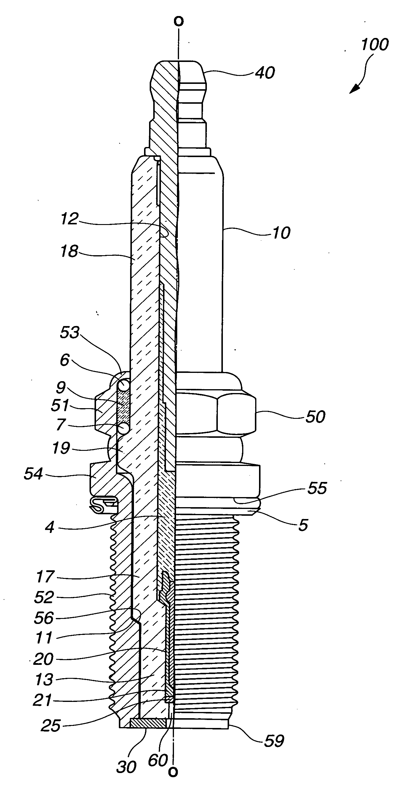
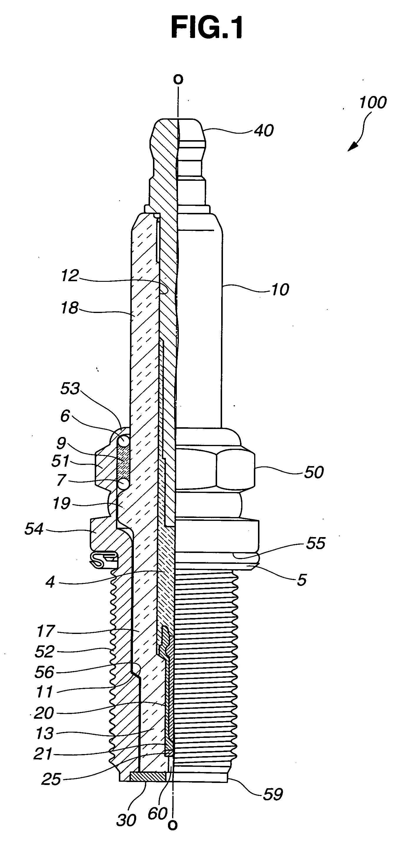
[0016] There is provided according to the first embodiment an ignition system for a four-cycle internal combustion engine including a plasma-jet spark plug 100 and an ignition control device 200. Hereinafter, the term “front” is used to indicate a spark discharge side (bottom side in FIG. 1) with respect to the axial direction ◯ of the spark plug 100 and the term “rear” is used to indicate a side (top side in FIG. 1) opposite to the front side.
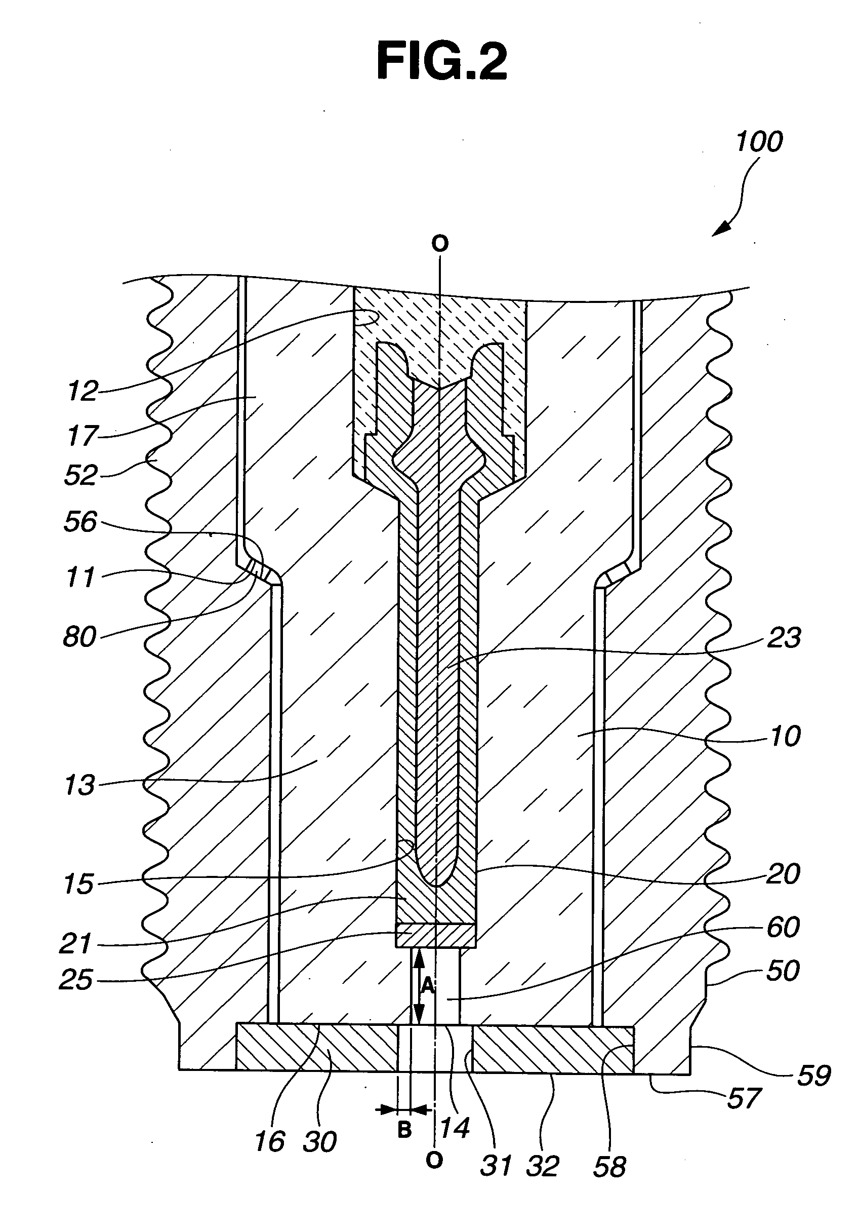
[0017] Referring to FIGS. 1 and 2, the spark plug 100 has a ceramic insulator 10 (as an electrical insulator), a metal shell 50 retaining therein the ceramic insulator 10, a center electrode 20 held in a front side of the ceramic insulator 10 along the axial direction ◯ of the spark plug 100, a ground electrode 30 joined to a front end 59 of the metal shell 50 to define a discharge gap between the center electrode 20 and the ground electrode 30 and a metal...
second embodiment
[0044] As shown in FIG. 5, the control circuits 220 and 240 determine the timing of receipt of the periodical ignition signal from the ECU as a primary ignition timing T15. Further, the control circuits 220 and 240 periodically receipt an ignition advance map (in which the intake / exhaust valve opening / closing timings, fuel injection timing and ignition timing are correlated to the ignition advance information from the crank angle sensor to adjust each of the valve opening / closing timings, fuel injection timing and ignition timing according to engine operating conditions), specifies an intake valve opening timing T11 and a fuel injection timing T14 based on the latest ignition advance map and the ignition signal receipt interval, and then, determines any appropriate point during the time period between the intake valve opening timing T11 and the fuel injection timing T14 as a secondary ignition timing T12. By way of example, the midpoint between T11 and T14 is determined as the secon...
PUM
 Abstract
Description
Claims
Application Information