Receiving apparatus, communication apparatus and control apparatus using the same

a communication apparatus and receiving device technology, applied in multiplex communication, synchronisation signal speed/phase control, amplitude demodulation, etc., can solve the problem of very small signal energy per unit frequency band, and achieve the effect of low cost and low power consumption

Active Publication Date: 2007-05-24
RENESAS ELECTRONICS CORP
View PDF4 Cites 25 Cited by
  • Summary
  • Abstract
  • Description
  • Claims
  • Application Information

AI Technical Summary

Benefits of technology

[0007] As the wireless system for short-range radio communication in low power consumption, the Bluetooth and Zigbee using the continuous wave of 2.4 GHz band are known, but the UWB-IR communication system can be expected in more effective signal transmission because of simple structure of apparatus in comparison with the Bluetooth. Moreover, the Zigbee is also useful in application to the sensor network from the viewpoint of transmission in low power consumption. However, the UWB-IR communication system has the merits that a high precision positioning function may be added which has been impossible in the Zigbee and rapid transfer rate can be realized in accordance with application while the low power consumption is maintained. As explained above, the UWB-IR communication system can be said as the radio communication technology which is expected to provide new communication services not attained from the existing wireless systems, from the view of low cost, low power consumption, common use of frequency band, and high precision positioning function.
[0017] Use of a matched filter is one of the methods to realize such initial acquisition of signal synchronization. This method enables rapid acquisition of signal synchronization but requires, on the other hand, a large-scale hardware. Particularly, when it is attempted to realize a matched filter using digital circuits in the UWB-IR communication system, analog to digital conversion and signal processes of several Gsps are required, resulting in increase of power consumption.
[0027] An object of the present invention lies in providing a low cost UWB-IR receiving apparatus which assuring low power consumption and higher communication performance.
[0028] Another object of the present invention lies in providing the UWB-IR receiving apparatus for realizing rapid and highly accurate initial acquisition of synchronization of the ultra-wide band signal without increase in complicatedness of hardware and in power consumption.
[0030] The present invention can provide, within the UWB-IR receiver, a synchronization acquisitioning function for rapidly and accurately searching the timing of the input pulse, thereby making it possible to provide a communication apparatus which assures low cost and low power consumption by controlling the frequency in the analog-to-digital conversion to a lower. frequency.

Problems solved by technology

As a result, signal energy per unit frequency band becomes very small.

Method used


Image

  • Receiving apparatus, communication apparatus and control apparatus using the same
  • Receiving apparatus, communication apparatus and control apparatus using the same
  • Receiving apparatus, communication apparatus and control apparatus using the same

Examples


first embodiment

[0063] The first embodiment of the receiving apparatus in the present invention will be explained with reference to FIG. 1 to FIG. 12.

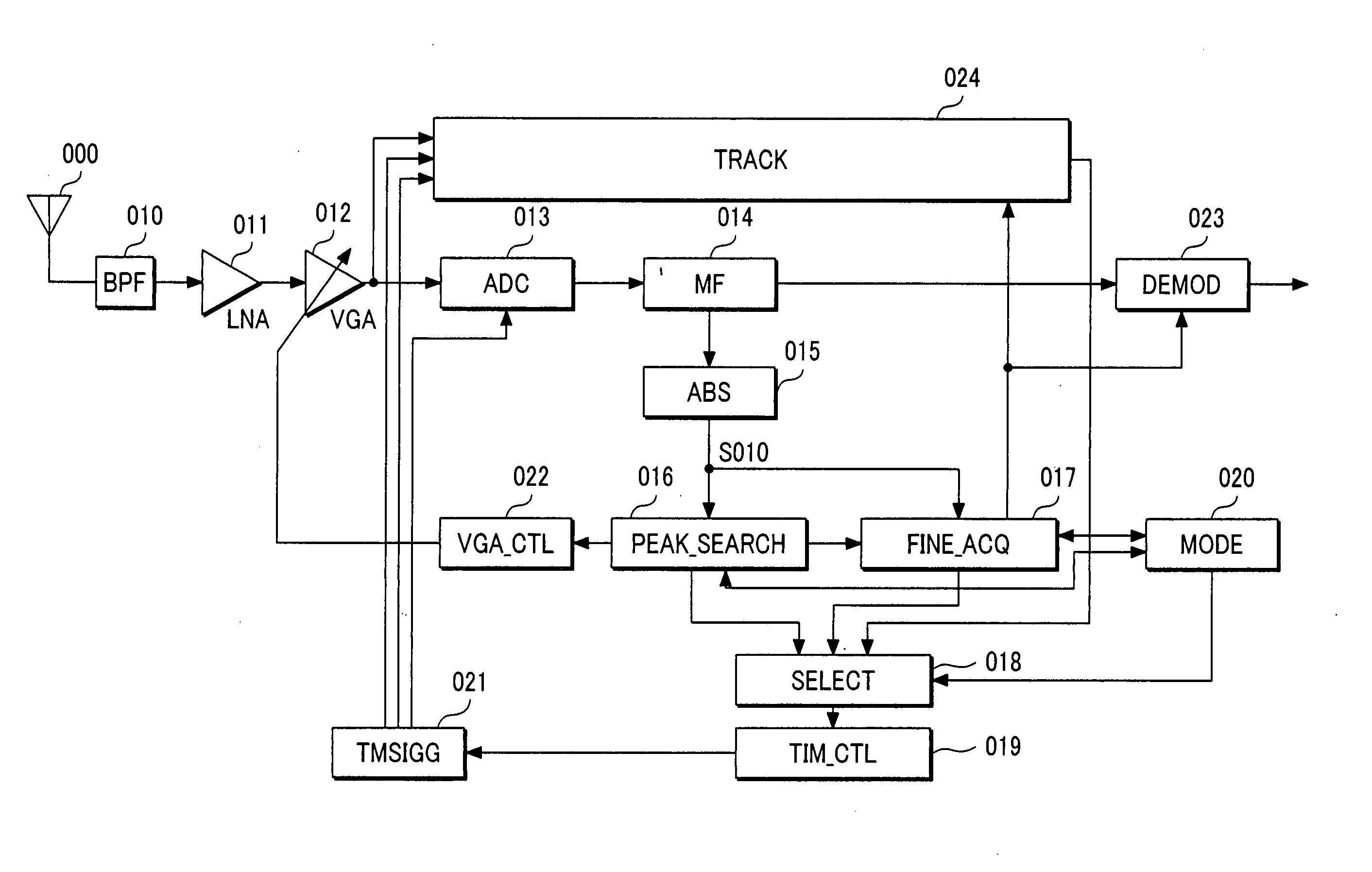
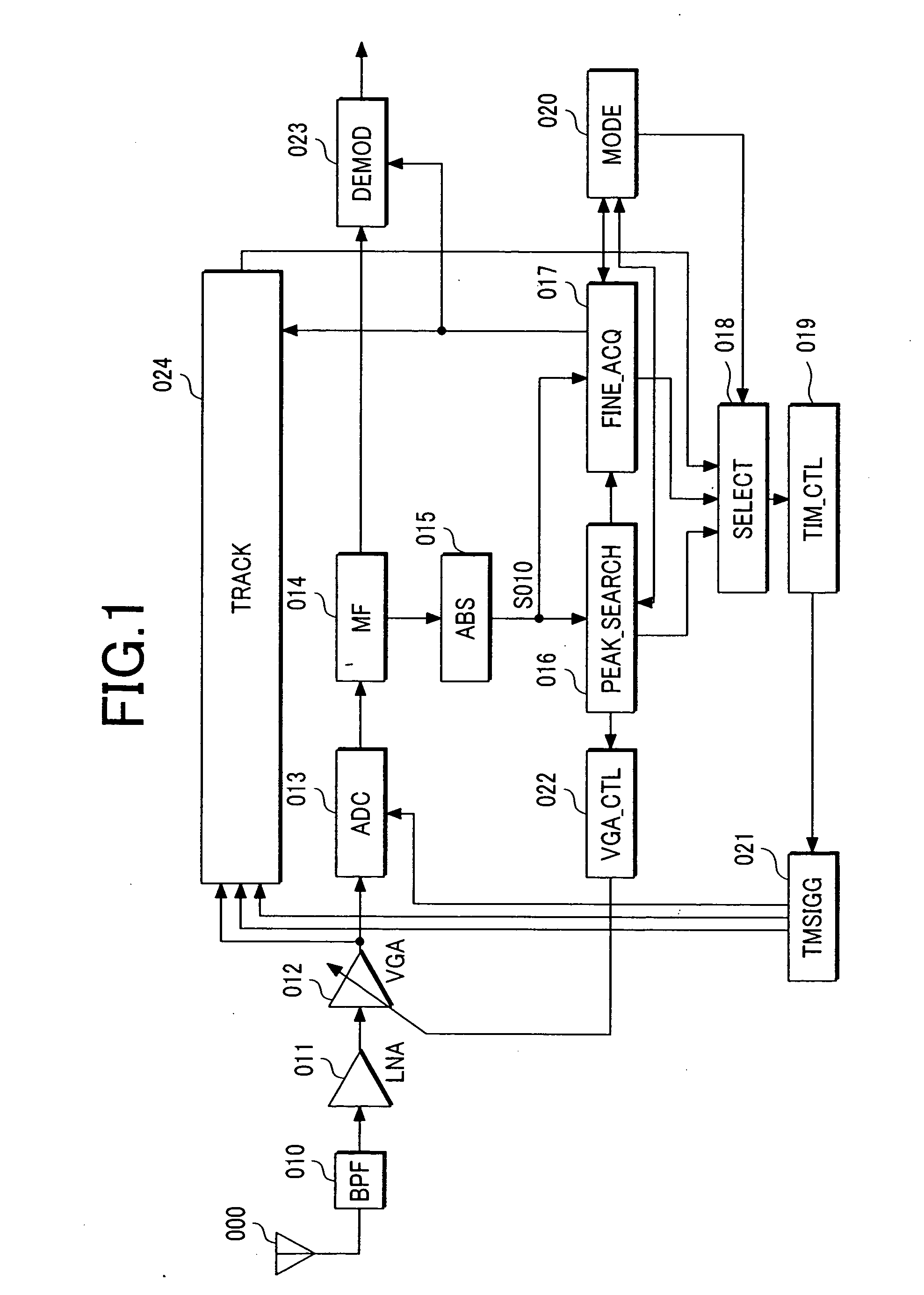
[0064] First, FIG. 1 is a schematic block diagram of the receiving apparatus in the first embodiment of the present invention. In FIG. 1, the receiving apparatus includes an antenna 000, a band-pass filter (BPF) 010, a low-noise amplifier (LNA) 011, a variable gain amplifier (VGA) 011, an analog-to-digital converter (ADC) 013, a matched filter (MF) 014, absolute value unit 015, a peak searcher 016, a detailed synchronization acquiring unit 017, a selector 018, a timing controller 019, a mode controller 020, a timing signal generator 021, a VGA controller 022, a demodulator 023, and a synchronization tracking unit 024.

[0065] The signal received by the receiving apparatus in the present invention through the antenna 000 is, for example, a BPSK-modulated and directly spread pulse (impulse) train signal as shown in FIG. 26A transmitted by the transmitti...

second embodiment

[0135]FIG. 13 is a schematic block diagram of the receiving apparatus in the second embodiment of the present invention. This embodiment is applied to a communication system for transmitting the signal using the modulated pulse waveform modulated obtained by modulating the carrier with the pulse waveform as shown in FIG. 26B transmitted, for example, by the transmitting apparatus shown in FIG. 25.

[0136] In FIG. 13, the receiving apparatus includes an antenna 000, a low-noise amplifier (LNA) 011, mixers 110I, 110Q, low-pass filters (LPFs) 111I, 111Q, variable gain amplifiers (VGAs) 012I, 012Q, analog-to-digital converters (ADCs) 013I, 013Q, matched filters (MFs) 014I, 014Q, an oscillator 113, a 90-degree phase shifter 114, a power calculator 115, a peak searcher 016, a detailed synchronization acquiring unit 017, a selector 018, a timing controller 019, a mode controller 020, a synchronous clock generator 083, a VGA controller 022, a demodulator 116 and a synchronization tracking un...

third embodiment

[0151] The third embodiment of the receiving apparatus of the present invention will be explained with reference to FIG. 15, FIG. 16, and FIG. 17. FIG. 15 is a schematic block diagram of the receiving apparatus in the third embodiment of the present invention. This embodiment is applied, for example, to a communication system for transmitting the signal using the modulated pulse waveform obtained by modulating the carrier with the pulse waveform as shown in FIG. 26B transmitted from the transmitting apparatus of FIG. 25.

[0152] In FIG. 15, the receiving apparatus includes an antenna 000, a low-noise amplifier(LNA) 011, mixers 110I, 110Q, low-pass filters (LPFs) 111I, 111Q, variable gain amplifiers (VGAs) 012I, 012Q, analog-to-digital converters (ADCs) 013I, 013Q, matched filters (MFs) 014I, 014Q, an oscillator 113, a 90-degree phase shifter 114, a power calculator 115, a peak searcher 210, a phase rotator 211, a detailed synchronization acquiring unit 017, a selector 018, a timing c...


PUM


Abstract

The present invention conducts the initial synchronization acquisition of the rapid and high precision ultra-wideband signal without complicatedness of hardware and increase in power consumption. For this purpose, a communication apparatus for exchanging information with an intermittent pulse train signal searches all phases among the pulses in the predetermined search resolution in the process to acquire initial synchronization of the input pulse, estimates the region where the peak phase of the largest output value exists, narrows the region where the peak phase exists up to the predetermined range by repeating the search for all phases in the estimated region in the next step, and conducts acquisition of detailed synchronization in the estimated region. In every step, the threshold value for judging existence of signal or a gain in the analog circuit is controlled for each step. Moreover, the search resolution is set coarse for estimation of the peak phase and set fine for acquisition of detailed synchronization.

Description

CLAIM OF PRIORITY [0001] The present application claims priority from Japanese application JP 2005-333670 filed on Nov. 18, 2005, the content of which is hereby incorporated by reference into this application. FIELD OF THE INVENTION [0002] The present invention relates to a receiving apparatus, a communication apparatus to form a communication system using an intermittent pulse train spread by spread code as the transmitting signal, and a control apparatus using the same and particularly to an ultra-wideband signal receiving apparatus and a communication apparatus provided with an initial signal acquisition apparatus for the same transmitting signal and a control apparatus using the same. BACKGROUND OF THE INVENTION [0003] In recent years, a radio terminal such as a mobile phone and a wireless LAN (Local Area Network) is remarkably spreading and the frequency band used is also extending up to GHz band. Therefore, it is now difficult to find out new frequency bands to be used. In the...

Claims


Application Information

Patent Timeline
Patent Type & Authority Applications(United States)
IPC IPC(8): H04B1/00H04L7/00H04B1/7183H04J13/00H04L7/10
CPCH04B1/7183H04L7/0058H04L7/10
Inventor FUJIWARA, RYOSUKENAKAGAWA, TATSUOMIYAZAKI, MASAYUKI
Owner RENESAS ELECTRONICS CORP
Why Eureka
Try Eureka