
Thermostructural turbomachine part that is circularly symmetrical about a longitudinal axis, the part including an annular wiper, and a method of manufacture

a technology of circular symmetry and turbine blades, applied in the direction of additive manufacturing apparatus, non-positive displacement fluid engines, liquid fuel engine components, etc., can solve the problems of inability to meet the stator in certain operating configurations, affecting the effect of affecting the effect of the winding

Active Publication Date: 2007-05-24
SN DETUDE & DE CONSTR DE MOTEURS DAVIATION S N E C M A
View PDF4 Cites 18 Cited by
  • Summary
  • Abstract
  • Description
  • Claims
  • Application Information

AI Technical Summary

Benefits of technology

[0011] An object of the present invention is to overcome that drawback by proposing a solution that makes it possible to avoid making a deposit by thermal spraying while nevertheless being able to make wipers that are not damaged by coming into contact with the abradable ring.
[0017] In this way, sawteeth are formed directly in the volume of the wiper, thereby making it easier to cut into the abradable material in comparison with a wiper constituted by a continuous blade.
[0019] The invention seeks to provide a method that makes it simple to fabricate such a wiper without having recourse to deposition by thermal spraying.
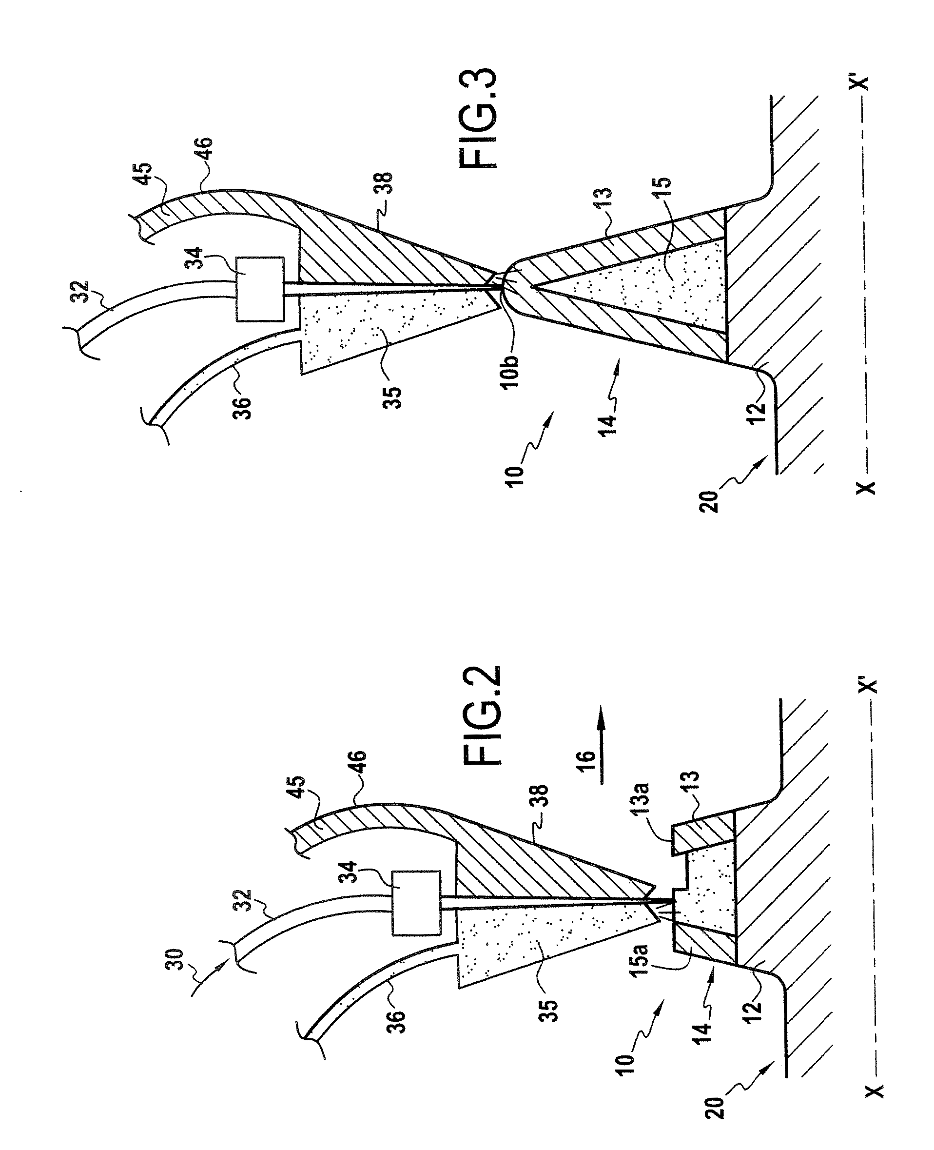
[0030] Laser spraying consists in using a laser beam that can be aimed very accurately to create a highly localized melt on the part, and in injecting into said melt a powder (made of metal and / or ceramic) that can be abrasive. Thus, unlike thermal spraying, there is no need to heat the powder, and its path can thus be separate from that of the laser beam.
[0036] In addition, with thermal spraying, a continuous coating method is provided, whereas with laser spraying, given the flexibility with which a laser beam can be controlled, it is possible to perform spraying either continuously or sequentially, merely by switching the laser beam on and off.
[0037] Furthermore, it will be understood that the solution in accordance with the present invention avoids any need to machine the tip of the wiper, where said tip is in a location that is relatively difficult for it to be machined. By means of the method of the present invention, the tip of the wiper is built up layer by layer, optionally simultaneously with a coating of a different material that is sufficiently abrasive.

Problems solved by technology

In particular, when they are continuous in shape, wipers are liable to come into contact with the stator in certain operating configurations.
In reality, the usual abradable materials can turn out to be relatively abrasive, in particular against certain continuous wipers, particularly if they are made of titanium-based alloy, but also if they are made of steel or of nickel-based alloy.
Amongst these situations, numerous circumstances arise that present a geometrical arrangement that makes deposition by thermal spraying very uncertain or practically impossible.
As a result, the abrasive coating is deposited preferentially only on the end (tip) of the wiper and as a result its flanks are poorly protected, which can lead to the wiper becoming worn more quickly.

Method used


Image

  • Thermostructural turbomachine part that is circularly symmetrical about a longitudinal axis, the part including an annular wiper, and a method of manufacture
  • Thermostructural turbomachine part that is circularly symmetrical about a longitudinal axis, the part including an annular wiper, and a method of manufacture
  • Thermostructural turbomachine part that is circularly symmetrical about a longitudinal axis, the part including an annular wiper, and a method of manufacture

Examples


Embodiment Construction

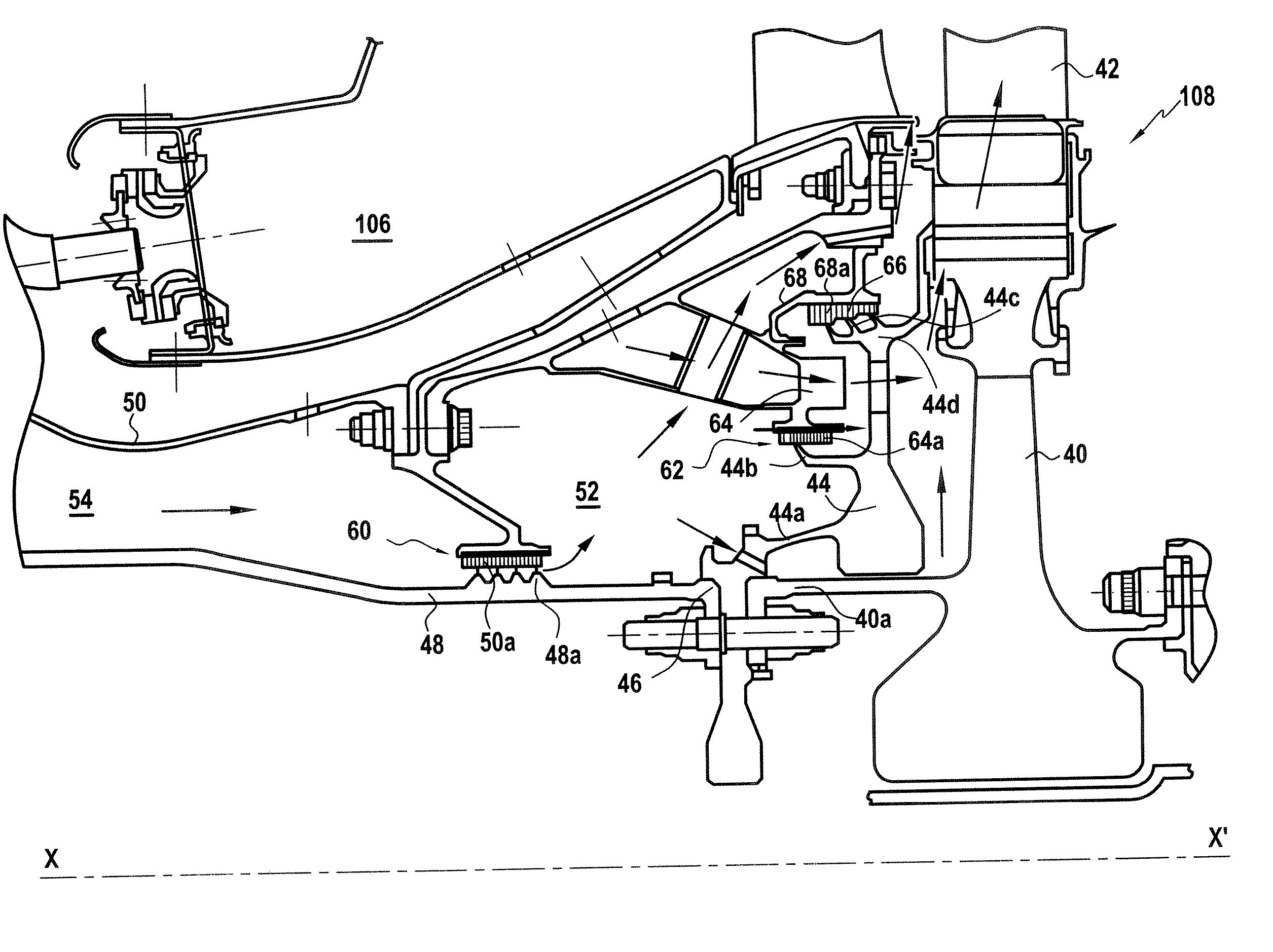
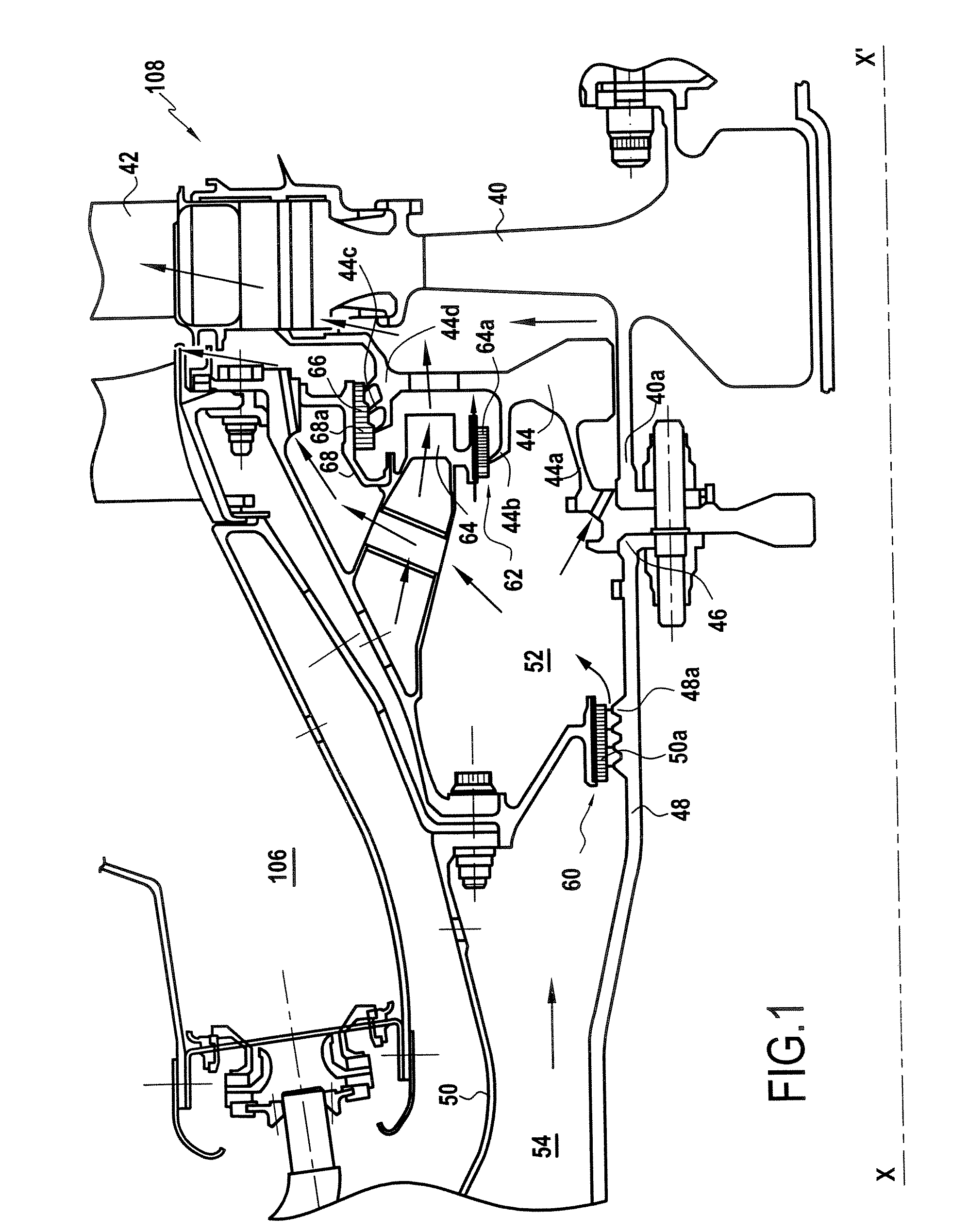
[0058] Since the present invention relates to sealing wipers for a circularly symmetrical thermomechanical part of a turbojet, in particular for a rotor, the description below relates to one possible and non-limiting application of a wiper of this shape in accordance with is the present invention.

[0059]FIG. 1 shows a circumstance in which the wipers are used in sealing labyrinths and are disposed facing abradable elements. It relates to a ventilation circuit for a high pressure turbine disposed downstream from a combustion chamber 106.

[0060] In particular, there is a turbine 108 having its circularly symmetrical rotor movable in rotation about an axis X-X′.

[0061] The rotor of the turbine 108 comprises a turbine disk 40 fitted with blades 42, and an end plate 44 disposed upstream from the disk 40. Both the disk 40 and the end plate 44 have a respective upstream flange referenced 40a for the disk 40 and 44a for the end plate 44, enabling them to be secured to the downstream end 46 ...


PUM

PropertyMeasurementUnit
Thicknessaaaaaaaaaa
Heightaaaaaaaaaa
Circumferenceaaaaaaaaaa

Abstract

In the method, a support is provided that presents a base for an annular wiper, and a wiper is built up that presents height that varies around its circumference, by forming a plurality of projecting portions by performing following successive steps: a laser source connected to an optical head focused on a point on the top surface of the base is activated, as is a source of powder connected to the spray nozzle, thereby forming a localized melt at said point, into which the powder is injected, thus forming a localized region of extra thickness; and the optical head and the nozzle are aimed at another point adjacent to said region of extra thickness and the method returns to the preceding step until the layer of material is completed in the angular sector in question.

Description

BACKGROUND OF THE INVENTION [0001] A sealing labyrinth, also known as a labyrinth seal, comprises a rotary portion having fins (or wipers) and a static bore covered in a soft abradable material or in a honeycomb structure capable of withstanding high temperatures. When the engine starts, the fins rub lightly against the lining, biting into it, thus leading to minimum spacing. This clearance varies over various cycles in flight, depending on the expansion of the part and on the natural flexibility of the moving portions. [0002] The wipers of labyrinths serve to provide aerodynamic sealing between enclosures containing air at different pressures. They are generally situated on the rotor portion facing stator portions. They are mainly constituted by continuous or segmented “blades” of annular shape, capable of being directed radially inwards or outwards. [0003] In particular, when they are continuous in shape, wipers are liable to come into contact with the stator in certain operating ...

Claims


Application Information

Patent Timeline
IPC IPC(8): F03B11/00
CPCB22F3/1055F01D11/02F04D29/023F04D29/102F16J15/445F16J15/4472F16J15/453Y02T50/67F05D2230/30F05D2260/95F05D2300/611F05D2230/31B33Y80/00B33Y10/00B29C64/153Y02P10/25B22F12/53B22F10/25B22F12/41Y02T50/60
Inventor MONS, CLAUDE MARCELVIGNEAU, JOEL OLIVIER ALFRED ABEL
Owner SN DETUDE & DE CONSTR DE MOTEURS DAVIATION S N E C M A
Learn More