Intervertebral anulus and nucleus augmentation

a technology of nucleus and annulus, which is applied in the field of surgical treatment of intervertebral discs, can solve the problems of increasing low back pain, reducing the degree of radicular symptoms, and reducing the patient's comfort, so as to reduce the height and pressure of the disc, prevent or minimize the extrusion of materials, and restore biomechanical function

Inactive Publication Date: 2007-05-24
INTRINSIC THERAPEUTICS
View PDF99 Cites 46 Cited by
  • Summary
  • Abstract
  • Description
  • Claims
  • Application Information

AI Technical Summary

Benefits of technology

[0026] Various embodiments of the present invention seek to exploit the individual characteristics of various anulus and nuclear augmentation devices to optimize the performance of both within the intervertebral disc. A primary function of anulus augmentation devices is to prevent or minimize the extrusion of materials from within the space normally occupied by the nucleus pulposus and inner anulus fibrosus. A primary function of nuclear augmentation devices is to at least temporarily add material to restore diminished disc height and pressure. Nuclear augmentation devices can also induce the growth or formation of material within the nuclear space. Accordingly, the inventive combination of these devices can create a synergistic effect wherein the anulus and nuclear augmentation devices serve to restore biomechanical function in a more natural biomimetic way. Furthermore, according to the invention both devices may be delivered more easily and less invasively. Also, the pressurized environment made possible through the addition of nuclear augmentation material and closing of the anulus serves both to restrain the nuclear augmentation and anchor the anulus augmentation in place.
[0028] One or more of the embodiments of the present invention additionally provide an anulus augmentation device that is adapted for use with flowable nuclear augmentation material such that the flowable material cannot escape from the anulus after the anulus augmentation device has been implanted.

Problems solved by technology

The most common resulting symptoms are pain radiating along a compressed nerve and low back pain, both of which can be crippling for the patient.
Nevertheless, the most significant drawbacks of discectomy are recurrence of herniation, recurrence of radicular symptoms, and increasing low back pain.
All of these failings are most directly related to the loss of NP material and AF competence that results from herniation and surgery.
Loss of NP material deflates the disc, causing a decrease in disc height.
Loss of disc height increases loading on the facet joints.
This can result in deterioration of facet cartilage and ultimately osteoarthritis and pain in this joint.
This leads to foraminal stenosis, pinching of the traversing nerve root, and recurring radicular pain.
Loss of NP also increases loading on the remaining AF, a partially innervated structure that can produce pain.
Finally, loss of NP results in greater bulging of the AF under load.
This can result in renewed impingement by the AF on nerve structures posterior to the disc.
Persisting tears in the AF that result either from herniation or surgical incision also contribute to poor results from discectomy.
This may over-stress the facets and contribute to their deterioration.
In these cases, not only is re-hemiation a risk but also leakage of fluids or solids from within the NP into the epidural space can occur.
This has been shown to cause localized pain, irritation of spinal nerve roots, decreases in nerve conduction velocity, and may contribute to the formation of post-surgical scar tissue in the epidural space.
Other orthopedic procedures involving removal of soft tissue from a joint to relieve pain have resulted in significant, long lasting consequences.
Partial and total meniscectomy leads to increased osteoarthritic degeneration in the knee and the need for further surgery in many patients.
The drawback of this method is that it is limited to the repair of a tear in soft tissue.
In the intervertebral disc, closure of a tear in the AF does not necessarily prevent further bulging of that disc segment toward the posterior neural elements.
However, all of the limitations pertaining to repair of intervertebral discs, as described above, pertain to this device.
The known embodiments and methods are limited in their application to hernias of the intervertebral disc in that they require a spring to apply tension.
Aside from the difficulty of placing a spring within the limited space of the intervertebral disc, a spring will induce a continuous displacement of the attached tissues that could be deleterious to the structure and function of the disc.
This has the drawback of requiring a second procedure.
This augmentation is limited in many ways.
First, by replacing the entire disc, they generally must endure all of the loads that are transferred through that disc space.
Many degenerated discs are subject to pathologic loads that exceed those in normal discs.
None of these augmentation devices has yet been able to achieve both qualities.
Further, devices that replace the entire disc must be implanted using relatively invasive procedures, normally from an anterior approach.
The limitation of these concepts is that the AF is often not intact in cases requiring augmentation of the disc.
There are either rents in the AF or structural weaknesses that allow herniation or migration of the disclosed implants.
In the case of a disc herniation, there are definite weaknesses in the AF that allowed the herniation to occur.
Augmenting the NP with any of the known augmentation devices without supporting the AF or implant risks re-herniation of the augmenting materials.
Further, those devices with deployable elements risk injuring the vertebral endplates or the AF.
Additionally, as the disc continues to degenerate, rents in the posterior anulus may occur in regions other than the original operated site.
A further limitation of these concepts is that they require the removal of much or all of the NP to allow insertion of the implant.
This requires time and skill to achieve and permanently alters the physiology of the disc.
Implanting prostheses in specific locations within the intervertebral disc is also a challenging task.
The rigorous requirements presented by these limitations on access to and visualization of the disc are not well compensated for by any of the intradiscal prosthesis implantation systems currently available.
The known planar patches are limited in their application in the intervertebral disc by the disc's geometry.
In the disc, it is difficult to create such a cavity between the inner wall of the anulus and the NP without removing nucleus material.
Such removal may be detrimental to the clinical outcome of disc repair.
However, placing a plug into the AF that must resist much higher pressures may result in expulsion of the plug or dissection of the inner layers of the anulus by the NP.
Either complication would lead to extraordinary pain or loss of function for the patient.
Further, a hernia in the intervertebral disc is likely to spread as the AF progressively weakens.
This device may be well suited for inguinal hernias, but the shape and stiffness of the disclosed embodiments are less than optimal for application in hernias of the intervertebral disc.
A disadvantage of this device is that the balloon must remain inflated for the remainder of the patient's life to insure closure of the defect.
Implanted, inflated devices rarely endure long periods without leaks, particularly when subjected to high loads.
This method has the drawback of relying entirely on the integrity of the wall surrounding the defect to hold the patch in place.
The anulus is often weak in areas around a defect and may not serve as a suitable anchoring site.
Further, the planar nature of the patch has all of the weaknesses discussed above.
Such a filament, if it were to extend to the exterior of the disc, could lead to irritation of nerve roots and the formation of scar tissue in the epidural space.
Additionally, such devices and methods embodied for use in the vascular system require a space relatively empty of solids for the deployment of the interior anchor.
The prior art devices, however, suffer from multiple limitations that hinder their ability to work in concert to restore the natural biomechanics of the disc.
In this type of intervention, however, the cause of the diminished nucleus pulposus content remains untreated.
A disc environment with a degenerated anulus, or one having focal or diffuse lesions, is incapable of maintaining pressure to support load transmission from either the native nucleus or a prosthetic augmentation and will inevitably fail.
In these cases, such augmentation prostheses can bulge through defects, extrude from the disc, or apply pathologically high load to damaged regions of the anulus.

Method used


Image

  • Intervertebral anulus and nucleus augmentation
  • Intervertebral anulus and nucleus augmentation
  • Intervertebral anulus and nucleus augmentation

Examples


Embodiment Construction

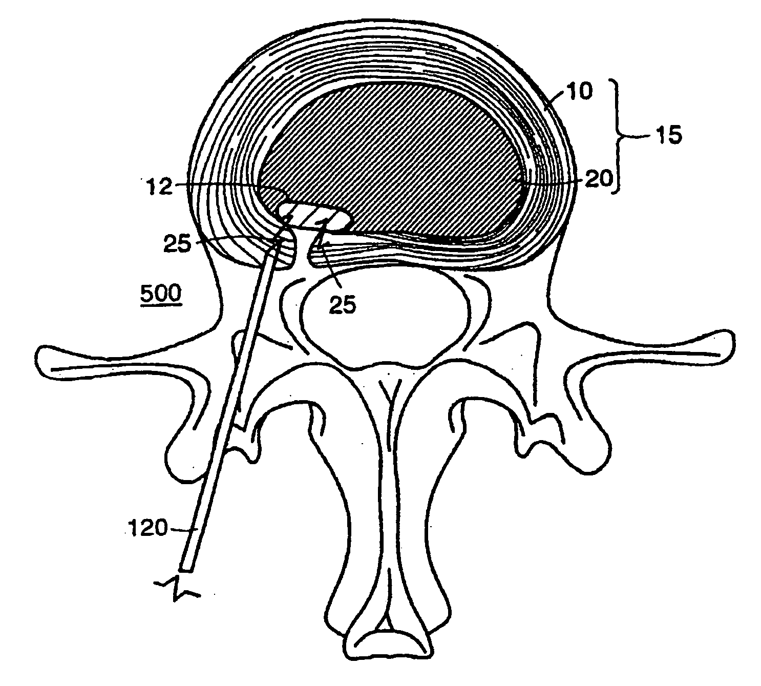
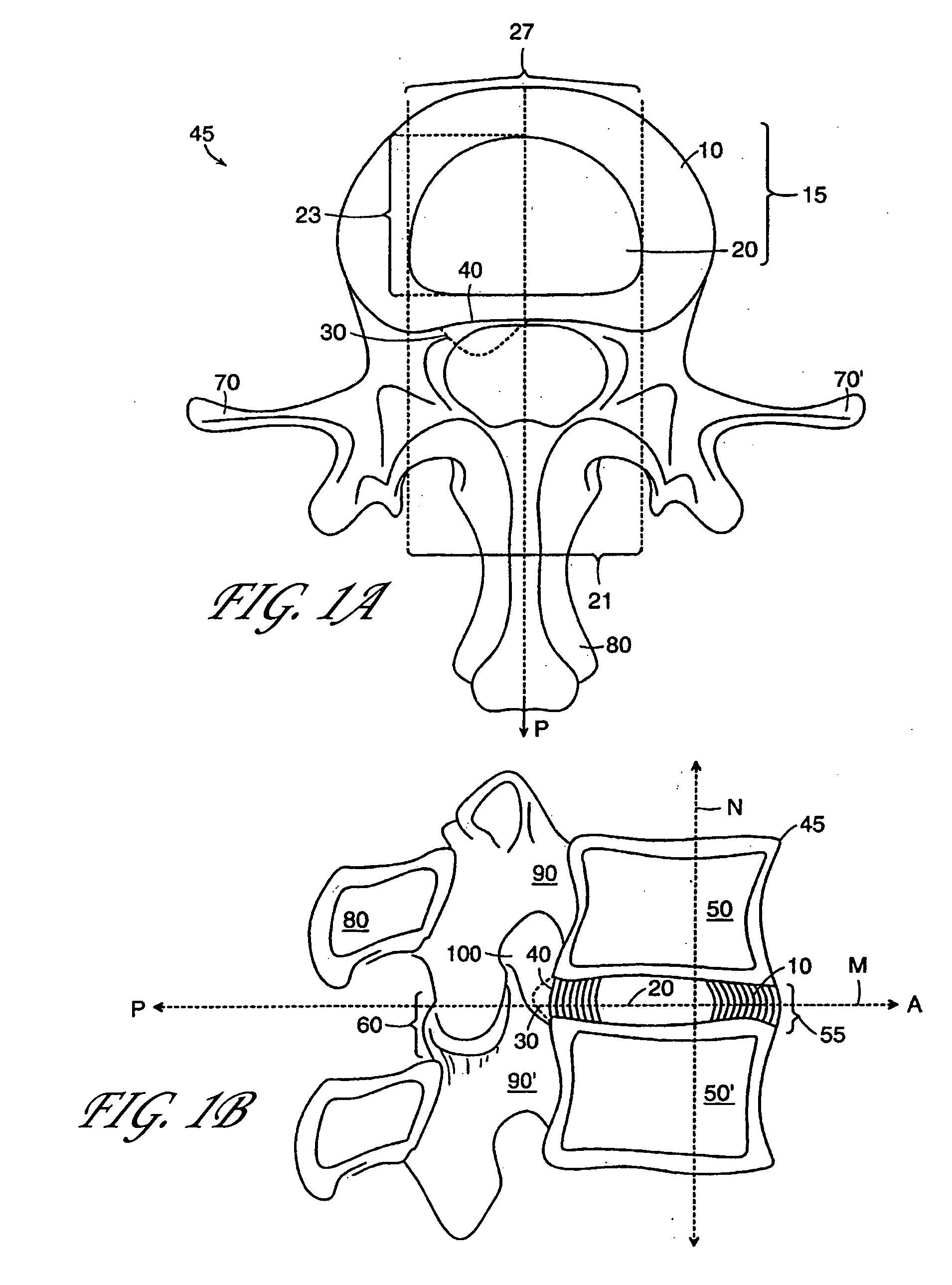
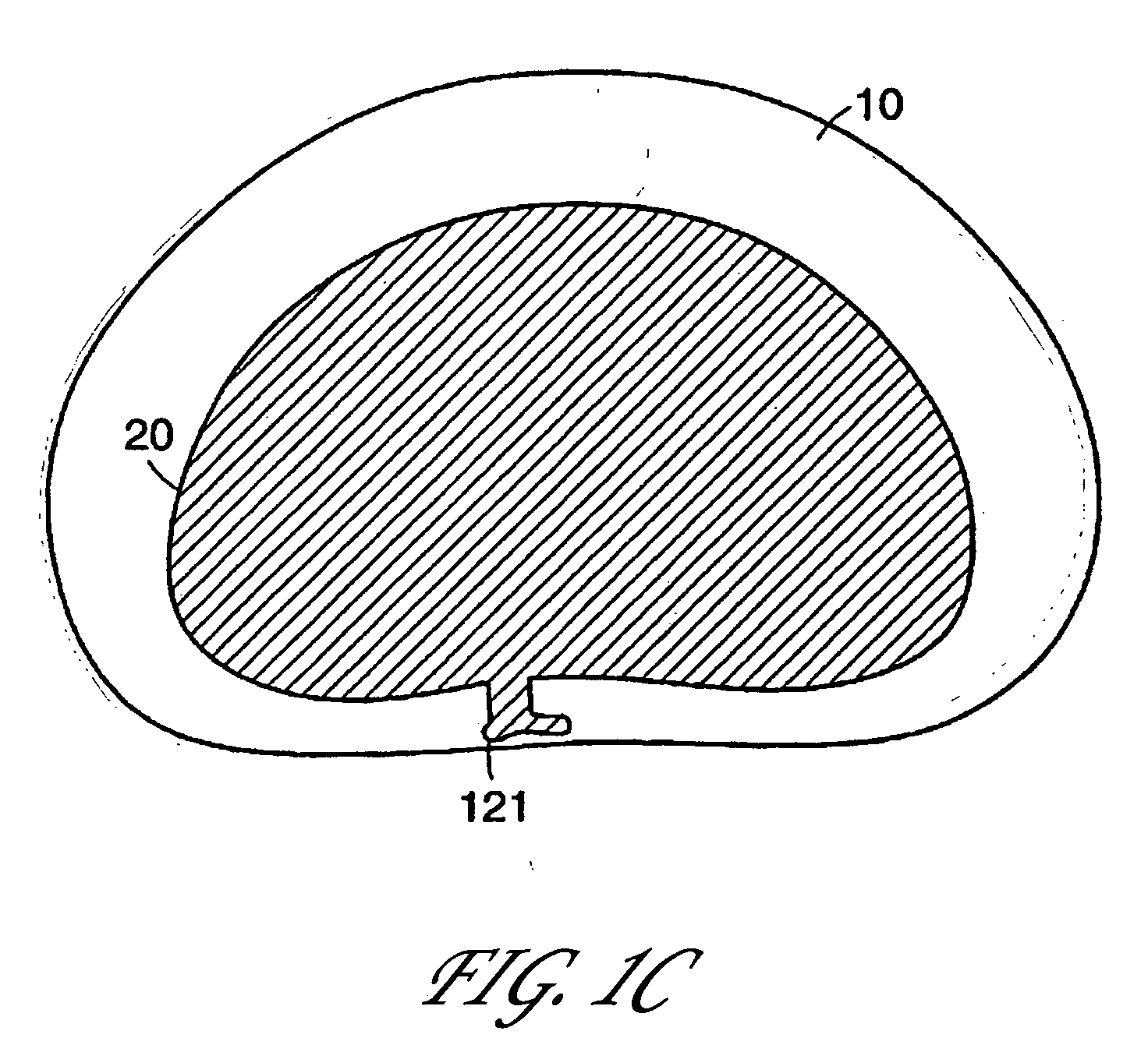
[0122] The present invention provides for an in vivo augmented functional spine unit. A functional spine unit includes the bony structures of two adjacent vertebrae (or vertebral bodies), the soft tissue (anulus fibrosis (AF), and optionally nucleus pulposus (NP)) of the intervertebral disc, and the ligaments, musculature and connective tissue connected to the vertebrae. The intervertebral disc is substantially situated in the intervertebral space formed between the adjacent vertebrae. Augmentation of the functional spine unit can include repair of a herniated disc segment, support of a weakened, torn or damaged anulus fibrosis, or the addition of material to or replacement of all or part of the nucleus pulposus. Augmentation of the functional spine unit is provided by herniation constraining devices and disc augmentation devices situated in the intervertebral disc space.

[0123]FIG. 1A and 1B show the general anatomy of a functional spine unit 45. In this description and the followi...


PUM


Abstract

Systems for minimally invasive disc augmentation include an anulus augmentation component and a nucleus augmentation component. Both are suited for minimally invasive deployment. The nucleus augmentation component restores disc height and / or replaces missing nucleus pulposus. The anulus augmentation component shields weakened regions of the anulus fibrosis and / or resists escape of natural nucleus pulposus and / or the nucleus augmentation component. Methods and deployment devices are also disclosed.

Description

RELATED APPLICATIONS [0001] This application is a continuation of co-pending U.S. application Ser. No. 10 / 055,504, filed on Oct. 25, 2001, which claims benefit to 60 / 311,586 filed Aug. 10, 2001 and which is a continuation-in-part of U.S. application Ser. No. 09 / 696,636 filed on Oct. 25, 2000, now issued as U.S. Pat. No. 6,508,839, which is a continuation-in-part of U.S. application Ser. No. 09 / 642,450 filed on Aug. 18, 2000, now issued as U.S. Pat. No. 6,482,235, which is a continuation-in-part of U.S. application Ser. No. 09 / 608,797 filed on Jun. 30, 2000, now issued as U.S. Pat. No. 6,425,919, which claims benefit to U.S. Provisional Application No. 60 / 172,996 filed Dec. 21, 1999, U.S. Provisional Application No. 60 / 161,085 filed Oct. 25, 1999, and U.S. Provisional Application No. 60 / 149,490 filed Aug. 18, 1999, the entire teachings of these applications being incorporated herein by reference.BACKGROUND OF THE INVENTION [0002] 1. Field of the Invention [0003] The present invention...

Claims


Application Information

Patent Timeline
Patent Type & Authority Applications(United States)
IPC IPC(8): A61F2/44A61B17/58A61B5/107A61B17/00A61B17/04A61B17/064A61B17/068A61B17/22A61B17/32A61B17/34A61B17/70A61B17/88A61B19/00A61F2/00A61F2/02A61F2/28A61F2/30A61F2/46A61L27/00A61M37/00
CPCA61B5/1076A61B5/4514A61B17/0057A61B17/0401A61B17/0469A61B17/0487A61B17/064A61B17/068A61B17/320016A61B17/320708A61B17/3468A61B17/70A61B17/7095A61B2017/00261A61B2017/00557A61B2017/00637A61B2017/00654A61B2017/00659A61B2017/00867A61B2017/044A61B2017/0458A61B2017/0488A61B2017/0496A61B2017/0647A61B2017/22077A61B2017/320044A61B2017/3445A61B2019/461A61B2019/462A61F2/2846A61F2/30723A61F2/30907A61F2/441A61F2/442A61F2/4601A61F2/4611A61F2/4657A61F2002/2817A61F2002/30062A61F2002/30075A61F2002/30131A61F2002/30224A61F2002/30228A61F2002/30291A61F2002/30462A61F2002/30571A61F2002/30583A61F2002/30589A61F2002/30677A61F2002/30777A61F2002/30785A61F2002/4435A61F2002/444A61F2002/448A61F2002/4627A61F2002/4635A61F2002/4658A61F2002/4661A61F2002/4662A61F2210/0004A61F2210/0061A61F2210/0085A61F2220/0075A61F2230/0013A61F2230/0069A61F2230/0091A61F2310/00017A61F2310/00023A61F2310/00029A61F2310/00293A61F2310/00365A61F2310/0097A61F2310/00976A61B2090/061A61B2090/062
Inventor LAMBRECHT, GREG H.MOORE, ROBERT KEVINEINHORN, JACOB
Owner INTRINSIC THERAPEUTICS
Why Eureka
Try Eureka