Al technical title is built by PatSnap Al team. It summarizes the technical point description of the patent document.
a technology of intervertebral discs and reinforcement systems, which is applied in the direction of prosthesis, catheters, applications, etc., can solve the problems of increasing low back pain, reducing the treatment effect, so as to resist fatigue and stress, the effect of reducing pain and minimising invasiveness
Inactive Publication Date: 2012-12-13
INTRINSIC THERAPEUTICS
View PDF0 Cites 49 Cited by
Summary
Abstract
Description
Claims
Application Information
AI Technical Summary
This helps you quickly interpret patents by identifying the three key elements:
Problems solved by technology
Method used
Benefits of technology
[0011]Several embodiments of the present invention relate generally to anulus augmentation devices, including, but not limited to, surgical meshes, barriers, and patches for treatment or augmentation of tissues within pathologic spinal discs. One or more embodiments comprise resilient surgical meshes that may be compressed for minimally invasive delivery and which are robust, stable, and resist fatigue and stress. These meshes are particularly well suited for intervertebral disc applications because they are durable enough to withstand intense cyclical loading and resist expulsion through a defect while not degrading over time.
Problems solved by technology
The most common resulting symptoms are pain radiating along a compressed nerve and low back pain, both of which can be crippling for the patient.
Nevertheless, the most significant drawbacks of discectomy are recurrence of herniation, recurrence of radicular symptoms, and increasing low back pain.
All of these failings are most directly related to the loss of NP material and AF competence that results from herniation and surgery.
Certain physiological environments present challenges to precise and minimally invasive delivery.
Also, the difficulty and danger of the implantation procedure itself, due to the proximity of the spinal cord, limits the size and ease of placement of the implant.
Method used
Image
Click on the blue label to locate the original text in one second.
Reading with bidirectional positioning of images and text.
Examples
Embodiment Construction
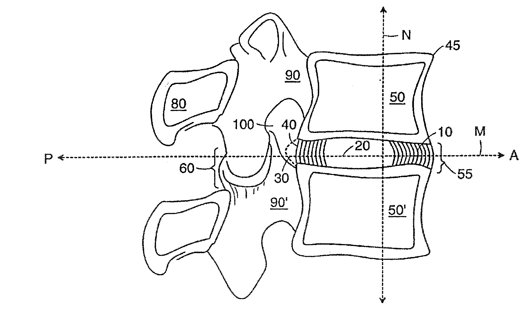
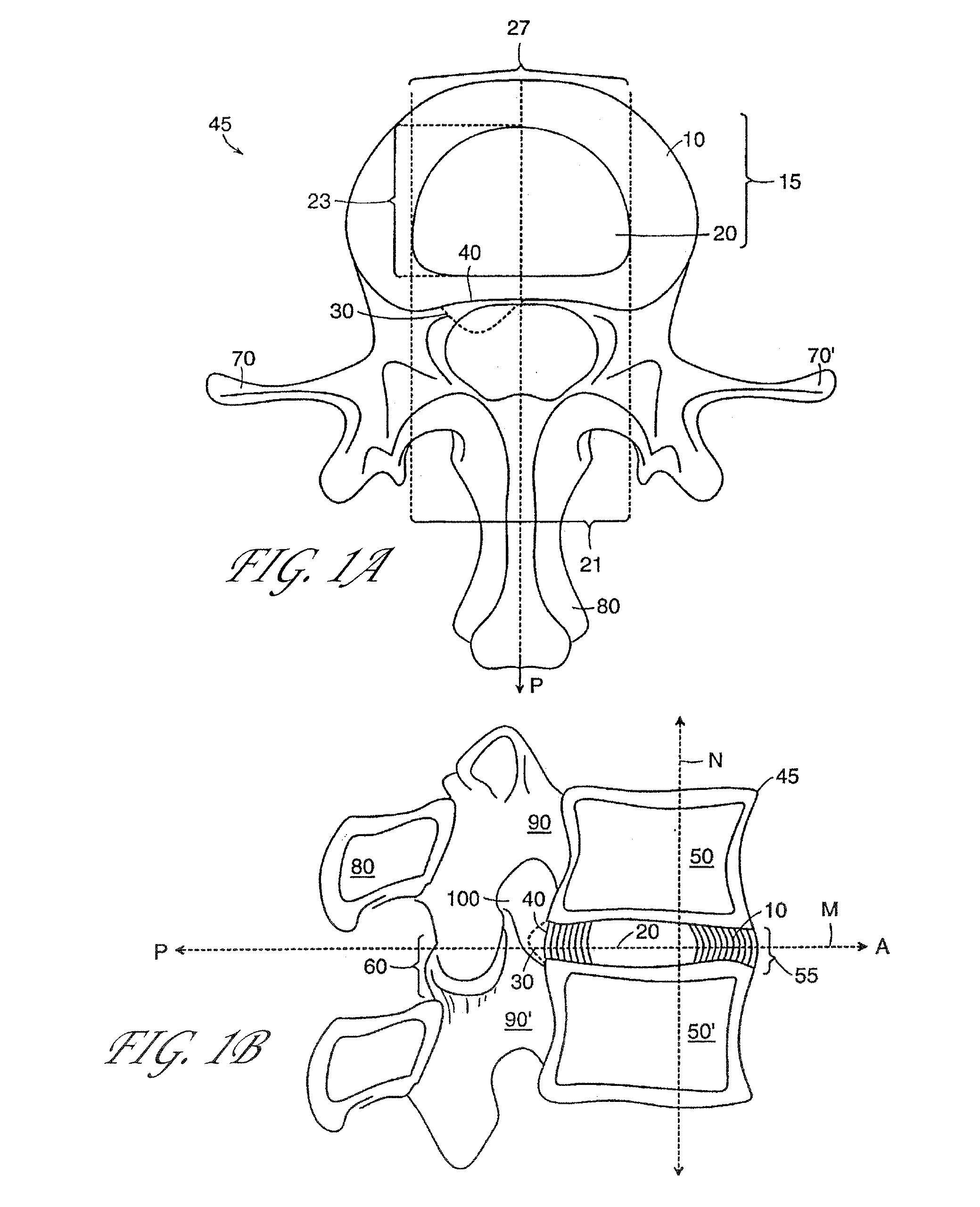
[0143]Several embodiments of the present invention provide for an in vivo augmented functional spine unit. A functional spine unit includes the bony structures of two adjacent vertebrae (or vertebral bodies), the soft tissue (anulus fibrosis (AF), and optionally nucleus pulposus (NP)) of the intervertebral disc, and the ligaments, musculature and connective tissue connected to the vertebrae. The intervertebral disc is substantially situated in the intervertebral space formed between the adjacent vertebrae. Augmentation of the functional spine unit can include repair of a herniated disc segment, support of a weakened, torn or damaged anulus fibrosis, or the addition of material to or replacement of all or part of the nucleus pulposus. Augmentation of the functional spine unit is provided by herniation constraining devices and disc augmentation devices situated in the intervertebral disc space.
[0144]FIGS. 1A and 1B show the general anatomy of a functional spine unit 45. In this descri...
PUM
Property
Measurement
Unit
length
aaaaa
aaaaa
volume
aaaaa
aaaaa
thickness
aaaaa
aaaaa
Abstract
An implant system for reinforcing an intervertebral disc and opposing endplate is provided wherein a flexible blocking member for blocking a defect is coupled to a first endplate anchor. An opposing endplate reinforcement member is coupled to a second endplate anchor and implanted in the opposing endplate.
Description
RELATED APPLICATIONS[0001]This application is a continuation-in-part of U.S. application Ser. No. 12 / 702,228, filed Aug. 12, 2010, which is a continuation of U.S. application Ser. No. 10 / 972,106, filed Oct. 22, 2004, now U.S. Pat. No. 7,658,765, which is a continuation of U.S. application Ser. No. 10 / 970,589, filed Oct. 21, 2004, now U.S. Pat. No. 7,553,329, which claims the benefit of U.S. Provisional Application No. 60 / 513,437, filed Oct. 22, 2003 and of U.S. Provisional Application No. 60 / 613,958, filed Sep. 28, 2004. U.S. application Ser. No. 10 / 970,589 is a continuation-in-part of U.S. application Ser. No. 10 / 194,428, filed Jul. 10, 2002, now U.S. Pat. No. 6,936,072, and is a continuation-in-part of U.S. application Ser. No. 10 / 055,504, filed Oct. 25, 2001, now U.S. Pat. No. 7,258,700. U.S. application Ser. No. 10 / 055,504 is a continuation-in-part of U.S. application Ser. No. 09 / 696,636, filed Oct. 25, 2000, now U.S. Pat. No. 6,508,839, which is a continuation-in-part of U.S. a...
Claims
Application Information
Patent Timeline
Application Date:The date an application was filed.
Publication Date:The date a patent or application was officially published.
First Publication Date:The earliest publication date of a patent with the same application number.
Issue Date:Publication date of the patent grant document.
PCT Entry Date:The Entry date of PCT National Phase.
Estimated Expiry Date:The statutory expiry date of a patent right according to the Patent Law, and it is the longest term of protection that the patent right can achieve without the termination of the patent right due to other reasons(Term extension factor has been taken into account ).
Invalid Date:Actual expiry date is based on effective date or publication date of legal transaction data of invalid patent.
Patent Type & Authority Applications(United States)