Apparatus and method for reducing effects of coherent artifacts and compensation of effects of vibrations and environmental changes in interferometry

a technology of coherent artifacts and interferometers, applied in the field of interferometer apparatuses, can solve the problems of reducing backward “scatter” and still a problem, and achieve the effect of reducing systematic errors and reducing sensitivity

Inactive Publication Date: 2007-05-31
ZETETIC INST
View PDF37 Cites 5 Cited by
  • Summary
  • Abstract
  • Description
  • Claims
  • Application Information

AI Technical Summary

Benefits of technology

[0062] Another advantage of certain embodiments of the present invention is reduced systematic errors in a one-, a two-, or a three-dimensional image of a substrate obtained in interferometric metrology systems.
[0063] Another advantage of certain embodiments of the present invention is reduced sensitivity, i.e., only in second and higher order effects, to an overlay error of a spot in or on the substrate that is being imaged and a conjugate image of a conjugate pixel of a multipixel detector during the acquisition of the respective electrical interference values for each spot in and / or on a substrate imaged using interferometric metrology systems. Overlay errors are errors in the set of four conjugate images of a respective set of conjugate detector pixels relative to the spot being imaged for either the bi-homodyne or quad-homodyne detection methods.
[0064] Another advantage of certain embodiments of the present invention is that the phase of an input beam component does not affect values of measured conjugated quadratures when operating in a frequency or temporal encoded mode of either the bi-homodyne or quad-homodyne detection methods.
[0065] Another advantage of certain embodiments of the present invention is the measurement of relative changes in position, orientation, and / or deformation between the reference and measurement objects based on phase measurements mod 2π.
[0066] Another advantage of certain embodiments of the present invention is the compensation for the residual effects of vibration and environmental changes including the effects of rotation and deformation in measured arrays of conjugated quadratures.
[0067] Another advantage of certain embodiments of the present invention is the control of the relative positions, orientations, and / or deformations of the reference and measurement objects using the measurements of relative changes in positions, orientations, and / or deformations between the reference and measurement objects based on phase measurements mod 2π.

Problems solved by technology

Generally, the sensitivity of these interferometers is such that it makes them adversely affected by background that can be produced by small imperfections in any practical system.
A problem with combining low temporal coherence with Fizeau interferometry is that with a reduced temporal coherence, only backward “scatter” is reduced whereas forward “scatter” is still a problem.
A quantity which causes the primary trouble with respect to coherent artifacts is the high spatial coherence of laser sources, not their high temporal coherence.
For Fizeau interferometer configurations with unequal path lengths and using the disk-like source, there is a trade-off between the amount of spatial coherence reduction that can be used and an undesired concomitant reduction of the contrast of interference fringes in an interferogram.
A disadvantage of this technique, however, is that it requires the averaging of a very large number of individual maps.
This often is not feasible because of the long data acquisition times required to achieve this.
A disadvantage of this technique, however, is the same as the disadvantage stated in the preceding paragraph with respect to U.S. Pat. No. 5,357,341.
One of the disadvantages of these methods is that multiple cameras are required or a single camera recording multiple images and complicated optical arrangements are required to produce the phase-shifted images.
Although the acquisition technology product FlashPhase™ is computationally complex, it is very fast on today's powerful computers.
However, the use of a tilted reference wave introduces departures from the common path condition that impacts of the problem presented by the effects of coherent artifacts.
However, one of the disadvantages of these grating methods is that careful adjustment of the position of the grating is required to control the phase shift between the beams.
However, this yet another method only measures the difference in height of two adjacent spots on a measurement object and not the simultaneous measurement of a two-dimensional array of spots on the measurement object.
A disadvantage of the techniques for generating simultaneous multiple phase shifted images described in U.S. Pat. No. 6,304,303 B1 is a first order sensitivity to variations in the relative sensitivities of conjugate sets of detector pixels and to variations in corresponding properties of the optical system used to generate the four phase shifted images wherein a conjugate set of pixels is four.
These types of sensors are disadvantageous in that they typically have much less sensitivity and spatial resolution than interferometric wavefront sensors.
The tilt in both cases is not used to generate information about the effect of the vibrations and environmental changes and in addition impacts on the problem presented by coherent artifacts.

Method used


Image

  • Apparatus and method for reducing effects of coherent artifacts and compensation of effects of vibrations and environmental changes in interferometry
  • Apparatus and method for reducing effects of coherent artifacts and compensation of effects of vibrations and environmental changes in interferometry
  • Apparatus and method for reducing effects of coherent artifacts and compensation of effects of vibrations and environmental changes in interferometry

Examples


first embodiment

[0151] The function of source 18 in the first embodiment may alternatively be served by use of a master-slave source configuration such as shown diagrammatically in FIG. 1d. With reference to FIG. 1d, the frequency of laser 1118 are controlled by a servo feedback as a component of signal 74 to control the frequency difference between the frequencies of master and slave lasers 118 and 1118, respectively. The frequency of laser 118 is controlled by a component of signal 74 from electronic processor and controller 80. A first portion of beam 120 generated by laser 118 is transmitted by a non-polarizing beam-splitter 148 as a first component of output beam 24 and a second portion of beam 120 is reflected by non-polarizing beam-splitter 148 as a first component of beam 1124. A first portion of Beam 1120 generated by laser 1118 is reflected by mirror 190 as beam 1122. A first portion of beam 1122 is reflected by non-polarizing beam-splitter 148 as a second component of output beam 24 and ...

second embodiment

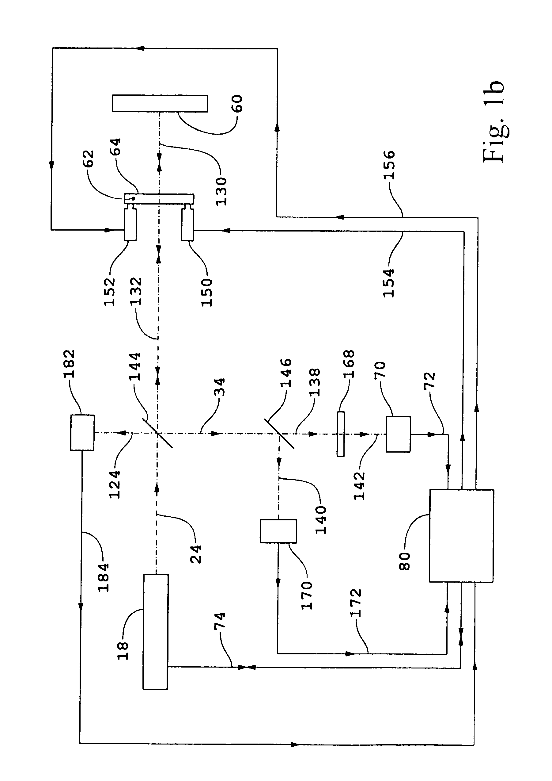
[0260] Continuing with the description of the second embodiment, output beam 34 is incident on non-polarizing beam-splitter 146 and first and second portions thereof transmitted and reflected, respectively, as beams 138 and 140, respectively. Beam 138 is detected by detector 70 preferably by a quantum process to generate electrical interference signal 72 after transmission by shutter 168 if required to generate beam 142 as a gated beam. Shutter 168 is controlled by electronic processor and controller 80. The function of shutter may be alternatively served by a shutter integrated into detector 70. Electrical interference signal 72 contains information about the difference in surface profiles of surfaces of reference object 68 and the reflecting surface of measurement object 1060.

[0261] Beam 140 is incident on and detected by detector 170 preferably by a quantum process to generate electrical interference signal 172 to generate the respective transmitted beam as a mixed beam. If beam ...


PUM


Abstract

An interferometric method including: generating a variable frequency source beam; from the source beam, generating a collimated beam propagating at an angle Ω relative to an optical axis; introducing the collimated beam into an interferometer that includes a reference object and a measurement object, wherein at least a portion of the collimated beam interacts with the reference object to generate a reference beam, at least a portion of the collimated beam interacts with the measurement object to generate a return measurement beam, and the reference beam and the return measurement beam are combined to generate a combined beam; causing the angle Ω to have a first value and at a later time a second value that is different from the first value; and causing the variable frequency F to have a first value that corresponds to the first value of the angle Ω and at the later time to have a second value that corresponds to the first value of the angle Ω.

Description

[0001] This application claims the benefit of U.S. Provisional Application No. 60 / 737,102, filed Nov. 15, 2005, which is incorporated herein by reference.TECHNICAL FIELD [0002] The invention in general relates to interferometric apparatus and methods for preserving test surface fringe visibility in interferograms while suppressing effects of coherent artifacts that would otherwise be present in the interferograms and for compensation of effects of vibrations and environmental changes in high speed measurements to improve overall signal-to-noise ratios. RELATED PATENT APPLICATIONS [0003] U.S. Ser. No. 11 / 463,036, filed Aug. 8, 2006, entitled “Apparatus and Methods for Reduction and Compensation of Effects of Vibrations and of Environmental Effects in Wavefront Interferometry” (ZI-71); and U.S. Ser. No. 11 / 457,025, filed Jul. 12, 2006, entitled “Continuously Tunable External Cavity Diode Laser Sources with High Tuning Rates and Extended Tuning Ranges” (ZI-72), both of which are incorp...

Claims


Application Information

Patent Timeline
Patent Type & Authority Applications(United States)
IPC IPC(8): G01B9/02
CPCG01N21/45G01B9/02004G01B9/02007G01B9/02059G01B9/02076G01B9/02057G01B9/02081G01B9/02083G01B2290/25G01B2290/65G01B2290/45
Inventor HILL, HENRY A.
Owner ZETETIC INST
Why Eureka
Try Eureka