
Single clutch transmission

a transmission and single clutch technology, applied in the field of transmission, can solve the problems of difficult to safely dock a boat, difficult to operate a boat, and a large number of problems, and achieve the effect of reducing drag and being extremely compa

Inactive Publication Date: 2007-06-07
CONSULTING INT
View PDF7 Cites 27 Cited by
  • Summary
  • Abstract
  • Description
  • Claims
  • Application Information

AI Technical Summary

Benefits of technology

[0037] Examples of the transmission system have the advantage of being extremely compact and of having only a single friction clutch, thus providing reduced drag compared with transmission systems incorporating more than one friction clutch. Advantageously, by virtue of the one way clutch, even if the system fails, forward drive is able to be transmitted via the transmission in at least one of the two speeds so that the system has a “limp-home” function enabling the boat owner to get the boat home.

Problems solved by technology

However a problem with this arrangement is that such craft are very difficult to operate at the low speeds that may be required for example, when docking the craft.
It is very difficult to dock a boat safely if, for example, the lowest speed that the boat will satisfactorily travel at, is around 10 knots.
Although a number of multi-speed drive transmissions have been proposed for watercraft, they suffer from a number of problems.
The transmission is based on a planetary gear apparatus and is consequently relatively high cost.
The transmission has a further problem in that because of the way the gearing is arranged, it is not possible to vary the gear ratios easily, since all the gear wheels must be changed.
It is thus harder to package and adapt planetary searing systems to slit different applications, engine sizes and the like.

Method used


Image

  • Single clutch transmission
  • Single clutch transmission
  • Single clutch transmission

Examples


Embodiment Construction

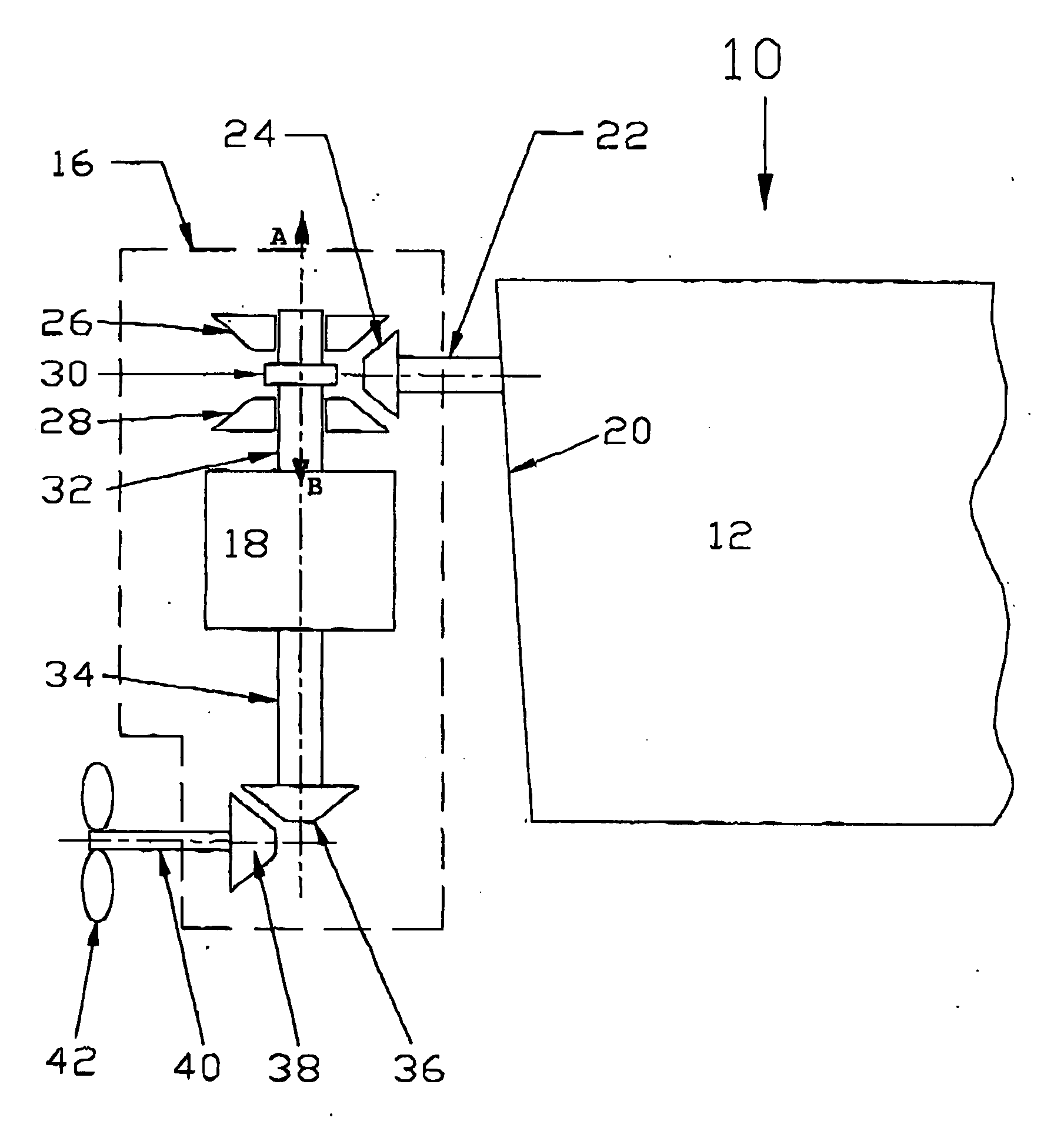
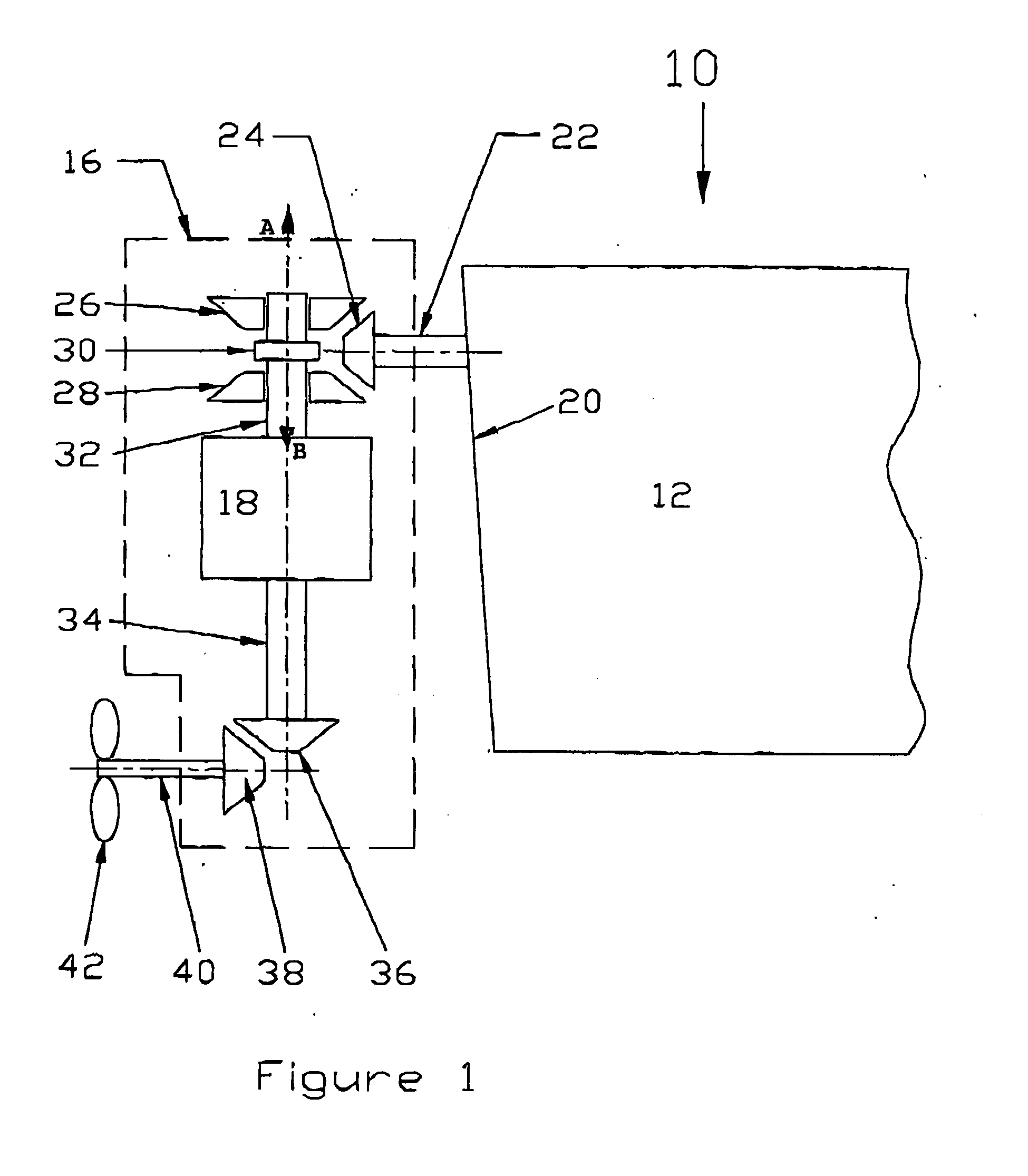
[0049] Referring to the drawings, FIG. 1 shows the stern of a watercraft 10 having a hull 12. A stern drive unit 16 incorporating a single friction clutch automated manual transmission 18 is located behind the transom 20 of the watercraft 10, an engine (not shown) is located inside the hull 12 and an output shaft 22 from the engine projecting generally horizontally from the stern of the watercraft provides power to the stern drive unit 16. This type of marine propulsion system is also commonly referred to as an “inboard / outboard drive”.

[0050] The output shaft 22 of the watercraft 10 spins about a generally horizontal axis. A bevel gear 24 is fixed to the end of the output shaft 22. The bevel gear 24 defined at the end of the output shaft 22 meshes with forward and reverse bevel gears 26, 28 respectively and a dog, or similar, clutch 30 moves in the direction of arrow “A” to connect a vertical output shaft 32 with the forward bevel gear 26, or in the direction “B” to connect the ver...


PUM


Abstract

A two speed transmission includes an input shaft; a lay shaft spaced from the input shaft; a first gear train connecting the input shaft to the lay shaft; a second gear train connecting the lay shaft to an output shaft the gear train including a one way clutch or similar; and a clutch for engaging the input shaft with the output shaft. The transmission is arranged such that when the output shaft is disengaged from the input shaft power is transmitted to the output shaft via the first and second gear trains and the lay shaft. When the clutch is disengaged, power is transmitted from the input shaft via the gear trains and the lay shaft via the one way clutch to the output shaft which typically provides first or low gear for use in low speed maneuvering or where greater torque is required. With the clutch engaged, power may be transmitted from the input shaft directly to the output shaft to provide a second gear for when the watercraft is cruising. This transmission system has the advantage of being extremely compact and since, it requires only a single clutch, provides reduced drag compared with transmission systems incorporating more than one clutch. Advantageously, the default for the transmission has the one way clutch or similar in the first or lower gear, with the clutch normally on, so that if the system fails, it is always possible for the boat owner to get the boat home albeit at a slower speed.

Description

CROSS-REFERENCE TO RELATED APPLICATIONS [0001] This invention claims priority from Australian provisional application No 2003903788 and also from U.S. provisional application No. 60 / 507,005. The entire contents of both documents are incorporated by reference. Priority is also claimed from a related provisional application filed by the same applicant / assignee Australian provisional application number 2004901167 the entire contents of which are also incorporated by reference.FIELD OF THE INVENTION [0002] The present invention relates to a transmission and in particular, the invention relates to an automated manual transmission which is particularly suited for use in marine applications. BACKGROUND OF THE INVENTION [0003] In most existing marine drives in watercraft, a marine engine is coupled to a propeller via a gear box which provides a single gear ratio. The speed of the watercraft is controlled by controlling the engine speed via a throttle. Generally speaking, watercraft are gear...

Claims


Application Information

Patent Timeline
IPC IPC(8): F16H61/00B63H23/06B63H23/30F16H3/091F16H3/10
CPCB63H20/14B63H23/06B63H23/08B63H23/30Y10T74/19605F16H3/10F16H2200/0034Y10T74/19223Y10T74/1926F16H3/0915F16H3/091
Inventor MOWBRAY, GRAHAMTAMBA, RICTAPPER, STEVE
Owner CONSULTING INT
Learn More