Wind blade assembly and method for damping load or strain

a technology of wind blades and components, applied in the direction of rotors, other chemical processes, vessel construction, etc., can solve the problems of slow reaction rate and achieve the effects of reducing load, slow reaction rate and cost of energy

Active Publication Date: 2007-06-07
GENERAL ELECTRIC CO
View PDF15 Cites 42 Cited by
  • Summary
  • Abstract
  • Description
  • Claims
  • Application Information

AI Technical Summary

Benefits of technology

[0007] The invention may also be embodied in a method for damping load or strain in the blades of a wind turbine blade assembly comprising a plurality of blades mounted on a hub, comprising: incorporating a piezoelectric damping system in or on each said blade, said piezoelectric damping system including at least one transducer assembly and at least one circuit electrically connected to said at least one transducer assembly, said circuit including at least one storage element configured to store power extracted from at least one said transducer assembly; storing power extracted from at least one said transducer assembly with said storage element; supplying said stored power back to at least one said transducer assembly; and converting said electrical power to mechanical power to actively stiffen said blade.

Problems solved by technology

Conventional pitch axis systems provide load relief to the structure in sustained high wind speed conditions, but their reaction rate is slow.

Method used


Image

  • Wind blade assembly and method for damping load or strain
  • Wind blade assembly and method for damping load or strain
  • Wind blade assembly and method for damping load or strain

Examples


Embodiment Construction

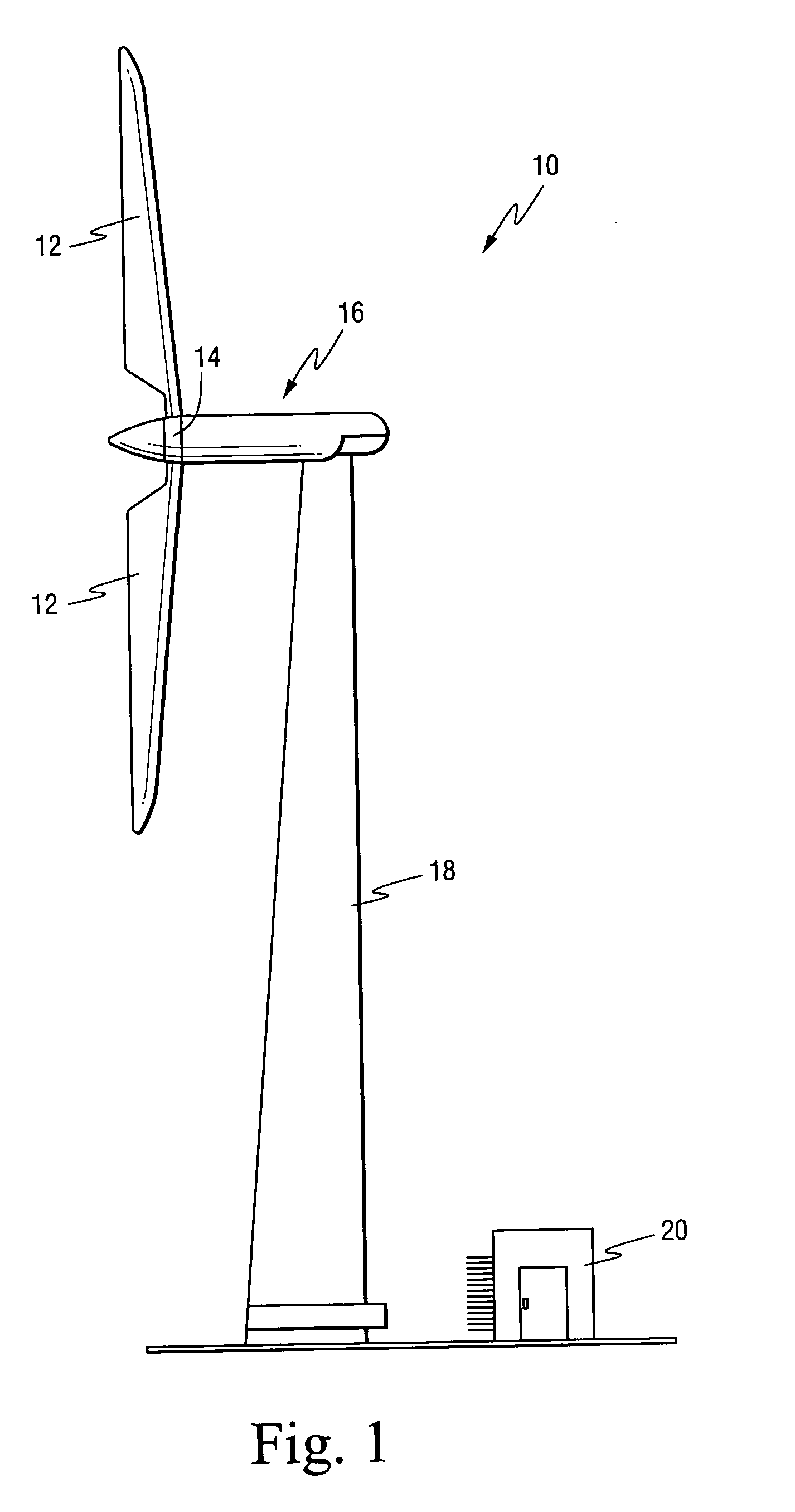
[0017] A wind turbine is schematically illustrated in FIG. 1. The turbine 10 generally includes a plurality of wind blades 12, for example two or three blades, attached to a hub 14. The blades are lightweight but stiff to reduce wind gusts. The blades may employ aerodynamic controls such as ailerons or windbrakes (not shown) to control speed. The hub is connected to a drive train (not shown) that may be flexible to minimize structural loads. This mechanism is connected to an electric generator 16. The entire mechanism is disposed on a tower structure 18 for exposure to stronger winds. A control room 20 is located at or near the turbine 10 and includes, or is operatively coupled to, a control computer to monitor wind conditions as well as current configurations and speed of the blades as detected by sensors (not shown in detail) provided on or associated with the turbine, and to implement control strategies.

[0018] Conventional pitch axis control has the ability to rotate the wind bl...


PUM


Abstract

The transducers are incorporated in or laminated to wind blades and electrically connected to a self-powered electrical circuit. The transducers in combination with the self-powered electrical circuit improve the wind blades' response to changing wind conditions by reducing loads, at least until the turbines pitch axis system can alter the lie of the blades. Thus, when there is a change in wind conditions, the resultant twisting or bending of the wind blade during the impact of the wind (gust) on the wind blade is used to extract energy from the transducers. This energy is then transferred to the electrical circuit which in turn sends a signal back to the transducers to actuate them so as to resist the imposed load.

Description

BACKGROUND OF THE INVENTION [0001] Piezoelectric materials can perform two desirable functions. When subjected to mechanical stress, e.g., bent, compressed or flexed, piezoelectric materials can generate an electric charge which can then be stored or used. Further, if an electric field is applied to a piezoelectric material, it can cause the piezoelectric material to deform. [0002] A manufacturing process has been developed for making piezoelectric ceramic materials into flexible fibers. More specifically, Advanced Cerametrics Inc. (ACI) has created a flexible lead zirconate titanate (PZT) ceramic fiber capable of harvesting energy, actively controlling structures or powering electronic systems. [0003] Piezoelectric fibers may be used in a “smart” sensor to sense the health of a structure or perform self-adjusting or vibration damping functions. In this regard, piezoelectric materials, such as ACI's PZT ceramic fibers, can be embedded into a composite material or attached to a struc...

Claims


Application Information

Patent Timeline
Patent Type & Authority Applications(United States)
IPC IPC(8): B64C27/615
CPCF03D1/0658F03D7/02F05B2220/709F05B2260/75F05B2260/96Y02E10/72Y10S416/50
Inventor DRIVER, HOWARD
Owner GENERAL ELECTRIC CO
Why Eureka
Try Eureka