[0020] One key feature of the invention is therefore that due to the flushing of at least parts of the tube with gas, i.e. for example sterile air,
dead volume can be effectively minimised, which is particularly important when using automated sampling. The excess fluid in the tubing can be sent back either to the reactor or into a sample tube or alternatively into a waste receptacle. Furthermore, the use of sterile air avoids
contamination of the tubing and dries it. Compared to manual sampling, the above automated sampling provides the following advantages: more consistent sample interval (automatically controlled), always fully identical taking of the sample,
reduced risk of
contamination due to
human error, increased safety and economical benefit. Additionally, the flushing of the tubing by a gas like sterile air allows to use long tubing without having to accept higher dead volumes. In particular in laboratories with restricted space, or if such a device is being used for sampling of various different bioreactors, tubes as long as 2 m or more between the sampler and the reactor are possible without detrimental effects.
[0021] In a first preferred embodiment of the present invention, said means are flushing the tube such that fluids in the tube are pushed back into the reactor after the sampling and / or that said means are flushing the tube such that fluids in the tube are pushed into the sampler for finishing the sampling. Since appropriate gas like sterile air is being used for flushing, pushing parts of the fluids back into the reactor does not detrimentally influence the reactions in the bioreactor. Nevertheless,
dead volume can be almost completely avoided. It can also be avoided, that fluids that might be stored in these tubes between individual sampling steps undergo further reaction / development which is different from the one in the bioreactor thus leading to a
distortion of the results. Optionally it is possible to flush the contents of the tube not back into the reactor but completely into a waste receptacle in case
contamination of the reactor might be a problem.
[0022] According to another preferred embodiment of the invention, the pump is connected with or integrated into the tube fluidly connecting said reactor with said sampler. Correspondingly, the pump is actually sucking the fluids, which may be a
fermentation broth, out of the reactor, and surprisingly, this process is even possible for highly viscous fluids and does not influence the broth. Preferentially at least one of the tubes is a flexible tube, preferably a
silicone tube. Using flexible tubes substantially facilitates autoclaving of the device, even more so if for control pinch valves are used with these tubes. A particularly controlled way of transporting fluids in such a
system can be achieved by using peristaltic pumps, which on the one hand transport fluids but on the other hand also act like a valve and prevent flux of gas or liquid if not operating.
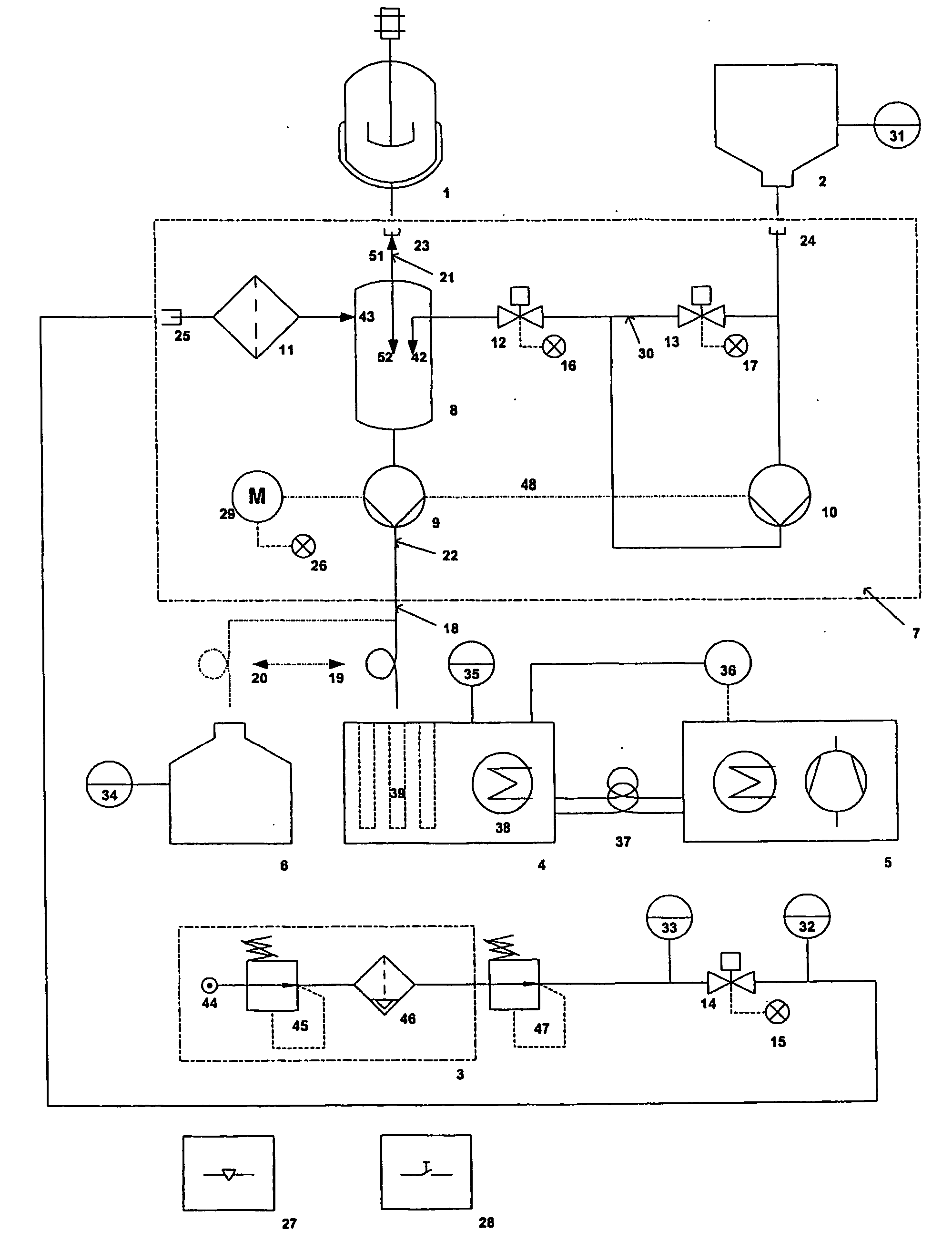
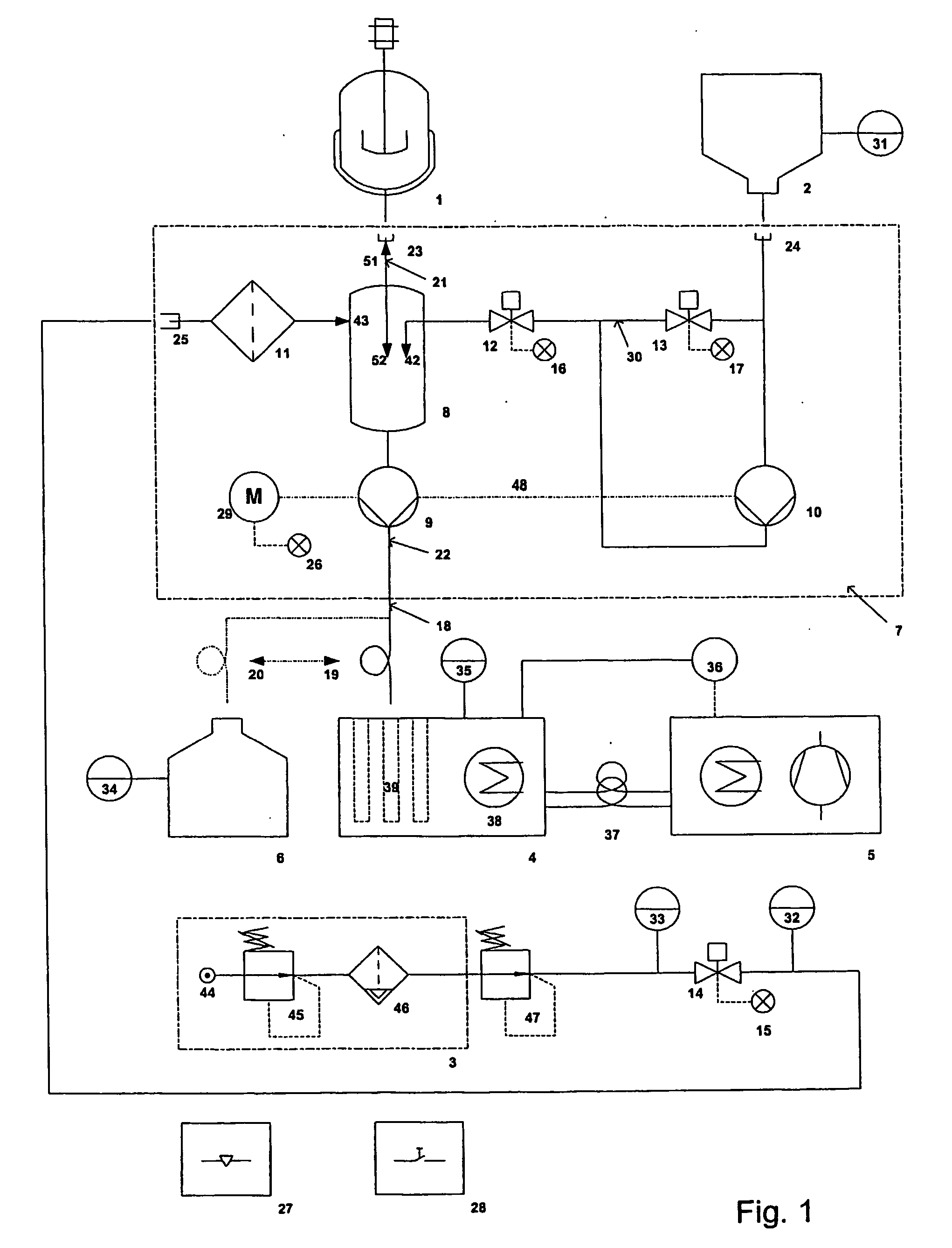
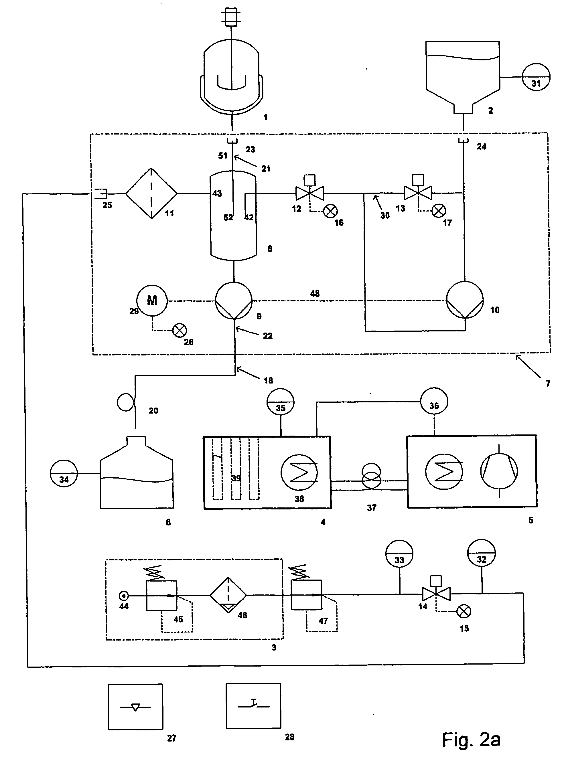
[0023] According to another preferred embodiment, there is provided a
biomass breaker, which generally stands for some kind of (sterile) trap (e.g. sterilisable closed funnel), which on its upper part is connected with the reactor by a first tube and which on its bottom is connected with the sampler by a second tube. Thus fluid entering from the reactor drops in by gravity and fluid in the
biomass breaker flows out by gravity in the direction of the sampler. Preferentially, the flushing air is also introduced into the system in the region of the
biomass breaker, namely in the upper part of the biomass breaker. Preferentially the second tube is a flexible tube and the pump is a
peristaltic pump acting upon said flexible tube. This set-up of the pump relative to the biomass breaker (i.e. downstream of the biomass-breaker in sampling direction) proves to be very effective and reduces dead volume problems while keeping
sterility at high levels.
[0024] Further improvements of the system are possible, if means are provided for introducing rinse solution (for increasing
sterility in particular in case of long studies or in case of studies prone to contaminations, e.g. animal
cell cultures) and / or inactivator solution (to stop or quench the processes in the fluid prior to deposition in the sample tubes) into at least parts of the ducts between individual sampling steps. Preferentially said solution is. introduced into the system in the biomass breaker, thus allowing in particular in case of an inactivator solution an effective mixing of the fluids with the inactivator solution. Optionally, there is provided at least one rinse / inactivator solution container connected with the biomass breaker by means of flexible tubes, wherein the flow of the solution is effected by a
peristaltic pump. Preferably the flow is controlled by means of pinch valves (with the above-mentioned advantages), and optionally the
peristaltic pump for the rinse / inactivator solution is driven by the same shaft as the peristaltic pump for the fluids (thus necessitating only one motor and one control, and assuring equal dosage). In case of using only one motor for the two pumps the provision of a bypass maybe advisable for recirculating the solution when it shall not be mixed with the fluids and to avoid unnecessary loss of the solution.
[0025]
Automation can be farther increased by providing a waste receptacle for taking up undesired fluids, and in that parts of the tube can automatically be shifted from the sampler to this waste receptacle.

