Manufacturing method of pattern formed body and pattern formed body manufacturing apparatus

a manufacturing method and pattern technology, applied in the direction of printing machines, cleaning using liquids, instruments, etc., can solve the problems of low location accuracy, material deterioration, and difficult use of methods, and achieve high pattern form accuracy, good wettability, and large contact angle

Inactive Publication Date: 2007-06-07
DAI NIPPON PRINTING CO LTD
View PDF8 Cites 14 Cited by
  • Summary
  • Abstract
  • Description
  • Claims
  • Application Information

AI Technical Summary

Benefits of technology

[0093] The kind of the variable property of the property variable layer in the pattern forming substrate is not particularly limited, and may be, for example, surface wettability variable by action of vacuum-ultraviolet light, adhesiveness to a specified substance variable by action of vacuum-ultraviolet light. In the invention, the property variable layer is preferably a layer the surface wettability of which is varied by action of vacuum-ultraviolet light, more preferably a wettability variable layer the contact angle of which with a liquid is lowered by action of vacuum-ultraviolet light. This makes it possible to render the area where the wettability is varied in the present step a lyophilic area and render the area where the wettability is not varied in the present step a liquid repellent area. Accordingly, when a functional part forming coating solution is coated onto a pattern formed body manufactured by the invention by, for example, a coating method, the functional part forming coating solution can be caused to adhere only to its property varied pattern, which is a lyophilic area. Consequently, a functional part can be made into a highly precise pattern form.
[0094] The lyophilic area is defined herein as an area having a lower contact angle with a liquid than that of any area adjacent thereto by 1° or more, and means an area which has a small contact angle with a liquid and has a good wettability to a functional part forming coating solution for forming a functional part. The liquid repellent area means an area which has a large contact angle with a liquid and has a bad wettability to the functional part forming coating solution.
[0095] The wettability variable layer used in the pattern forming substrate preferably has a contact angle of 10° or more with the liquid having a surface tension of 40 mN/m, and more preferably has a contact angle of 10° or more with the liquid having a surface tension of 20 mN/m in the state that the wettability of the layer is n

Problems solved by technology

However, the above-mentioned printing methods have: a problem that at the time of manufacturing a highly precise pattern formed body, which is used in such as a color filter, only a low location accuracy is attained; and other problems.
Thus, it is difficult to use the methods.
The above-mentioned photolithography has: a problem that it is necessary to dispose of waste liquid since a photoresist is used and the photoresist i

Method used


Image

  • Manufacturing method of pattern formed body and pattern formed body manufacturing apparatus
  • Manufacturing method of pattern formed body and pattern formed body manufacturing apparatus
  • Manufacturing method of pattern formed body and pattern formed body manufacturing apparatus

Examples


example 1

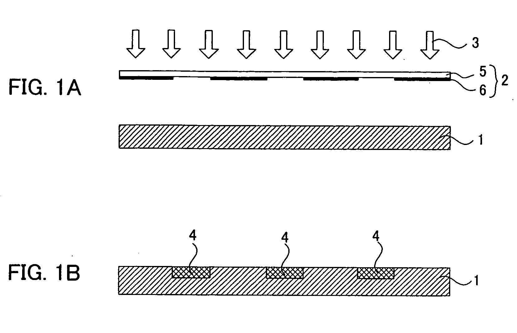
[0155] At room temperature, 1.5 g of a fluoroalkylsilane (TSL 8233, manufactured by GE Toshiba Silicone Co., Ltd.), 5.0 g of a tetramethoxysilane (TSL 8114, manufactured by GE Toshiba Silicone Co., Ltd.), and 3 g of 0.1 N hydrochloric acid were stirred for 24 hours to produce a liquid repellent agent containing fluorine. To 1 g of this liquid repellent agent was added 99 g of isopropanol, and then the solution was stirred at room temperature for 10 minutes. This diluted solution was coated onto a glass substrate with a spin coater (at 700 rpm for 5 seconds) to yield a pattern forming substrate on which a wettability variable layer having liquid repellency was formed.

[0156] The pattern forming substrate and a photomask having a pattern with alternately-arranged lines and spaces each having a line width of 20 μm were opposed to each other so as to have an interval of 1 μm therebetween, and an excimer lamp was used to radiate vacuum-ultraviolet light through the photomask onto the pat...

example 2

[0159] In the same way as in Example 1, a pattern forming substrate in which a wettability variable layer having liquid repellency was formed was produced.

[0160] The pattern forming substrate and a photomask having a pattern with alternately-arranged lines and spaces each having a line width of 50 μm were opposed to each other so as to have an interval of 10 μm therebetween, and an excimer lamp was used to radiate vacuum-ultraviolet light through the photomask onto the pattern forming substrate for 40 seconds. As a result, a line pattern, as a lyophilic area, in which its line widths were each 50 μm was formed.

[0161] Subsequently, the following was performed as a foreign matter removing step: the surface side of the exposed photomask which was opposed to the pattern forming substrate was sucked under a pressure of 100 mmHg for 3 minutes. Thereafter, in a subsequent pattern-forming step, vacuum-ultraviolet light was radiated through the photomask, which underwent the above-mentione...

example 3

[0163] In the same way as in Example 1, a pattern forming substrate in which a wettability variable layer having liquid repellency was formed was produced.

[0164] The pattern forming substrate and a photomask having a pattern with alternately-arranged lines and spaces each having a line width of 15 μm were opposed to each other so as to have an interval of 2 μm therebetween, and an excimer lamp was used to radiate vacuum-ultraviolet light through the photomask onto the pattern forming substrate for 90 seconds. As a result, a line pattern, as a lyophilic area, in which its line widths were each 15 μm was formed.

[0165] Subsequently, the following was performed as a foreign matter removing step: wind having a wind speed of 8.5 m / second (measured with a vane type anemometer in a measurement range of 4 inches) was blown, for 4 minutes, onto the surface side of the exposed photomask which was opposed to the pattern forming substrate. Thereafter, in a subsequent pattern-forming step, vacu...


PUM


Abstract

A main object of the invention is to provide a a manufacturing method of a plurality of pattern formed bodies which makes it possible that even if the pattern formed bodies are continuously manufactured, their property varied patterns are each made into a target pattern form with high precision; and a pattern formed body manufacturing apparatus used in the manufacturing method. To achieve the object, the invention provides a manufacturing method of a plurality of pattern formed bodies comprising a pattern forming step and a foreign matter removing step, wherein the pattern forming step is a step of radiating vacuum-ultraviolet light through a photomask to a pattern forming substrate, varying a surface property by the vacuum-ultraviolet light, and forming a property varied pattern with the property varied on a surface of the pattern forming substrate to form a pattern formed body; the pattern forming step is repeated plural times to manufacture a plurality of the pattern formed bodies; and the foreign matter removing step is a step of removing a foreign matter deposited to the photomask performed between the repeated pattern forming steps.

Description

BACKGROUND OF THE INVENTION [0001] 1. Field of the Invention [0002] The present invention relates to a manufacturing method of a pattern formed body which has a surface property varied in a pattern form and is used in the manufacture of, for example, a color filter; and a pattern formed body manufacturing apparatus used in the manufacturing method. [0003] 2. Description of the Related Art [0004] Conventionally, various methods have been suggested as a manufacturing method of a plurality of pattern formed bodies in which designs, images, characters, circuits or other various patterns are formed on a base material. For example, there are also used lithographic printing, offset printing, a printing method of using a heat-mode recording material to produce a lithographic original master, and other methods. Moreover, there is known, for example, a manufacturing method of a pattern formed body, comprising the step of radiating light patternwise to a photoresist layer coated on a base mate...

Claims


Application Information

Patent Timeline
IPC IPC(8): G03B27/42G03F7/00G02B5/20G02F1/1335G03F1/72G03F1/74G03F7/20
CPCG03F1/82G03F1/84G03F7/0007
Inventor SAWADA, TAKASHIYAMASHITA, KAORIKOBAYASHI, HIRONORI
Owner DAI NIPPON PRINTING CO LTD
Why Eureka
Try Eureka