Refrigerant cooled main steam condenser

Inactive Publication Date: 2007-06-21
BROWN JR JOSEPH FRANCIS
View PDF9 Cites 3 Cited by
  • Summary
  • Abstract
  • Description
  • Claims
  • Application Information

AI Technical Summary

Benefits of technology

[0010]This invention was inspired by the rising energy costs and public concerns. Utilities pass-on much of the increased energy costs to the public. To improve the efficiency of the power source, is to, lower consumer costs. The refrigerant cooling system replacement of the present once thru cooling system will reduce these costs. The lower utility costs and the elimination of the cooling towers and hot water returns to the river or lake, will reduce public economic and environmental concerns.

Problems solved by technology

Utilities pass-on much of the increased energy costs to the public.

Method used


Image

  • Refrigerant cooled main steam condenser
  • Refrigerant cooled main steam condenser
  • Refrigerant cooled main steam condenser

Examples


Embodiment Construction

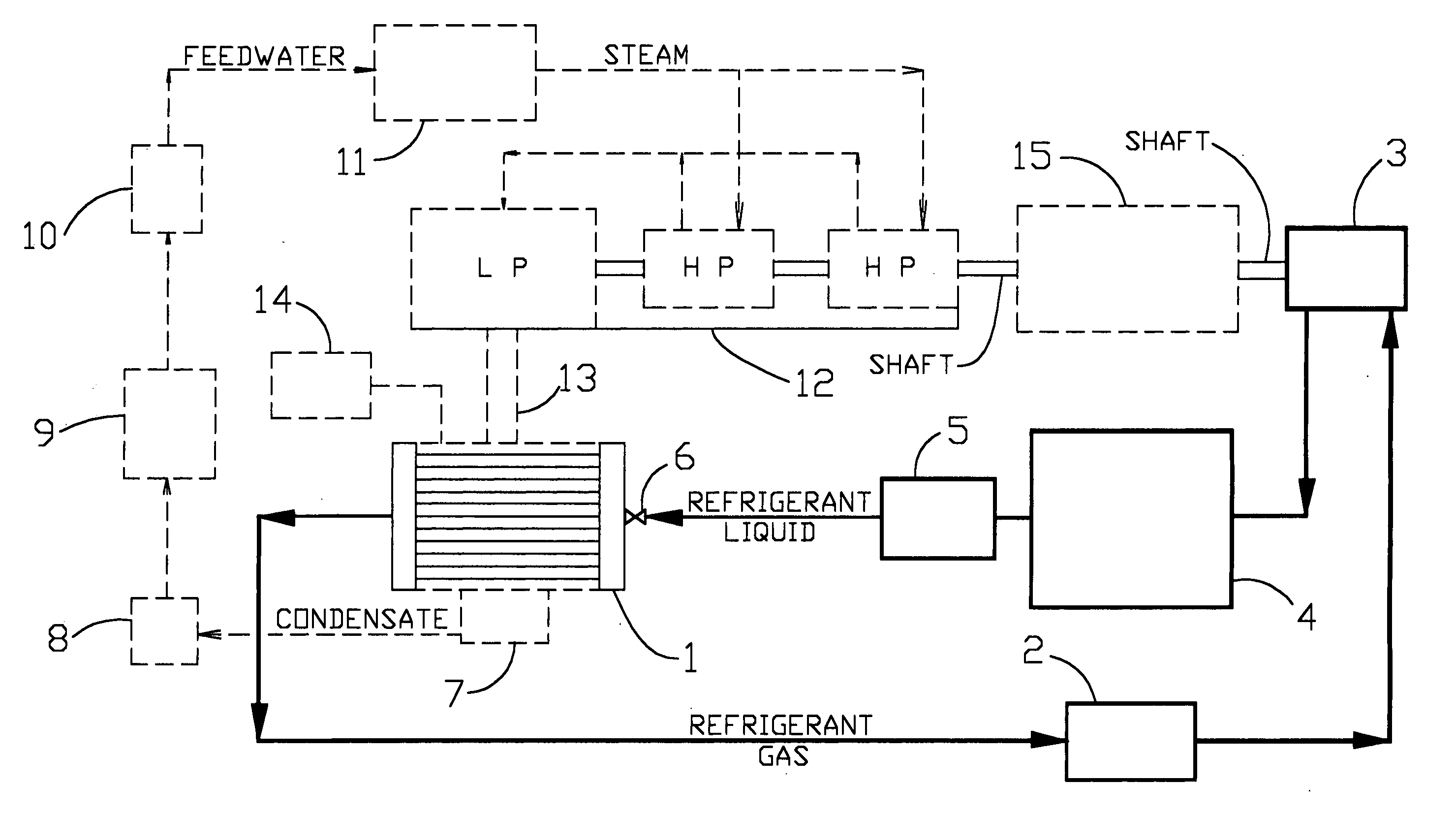
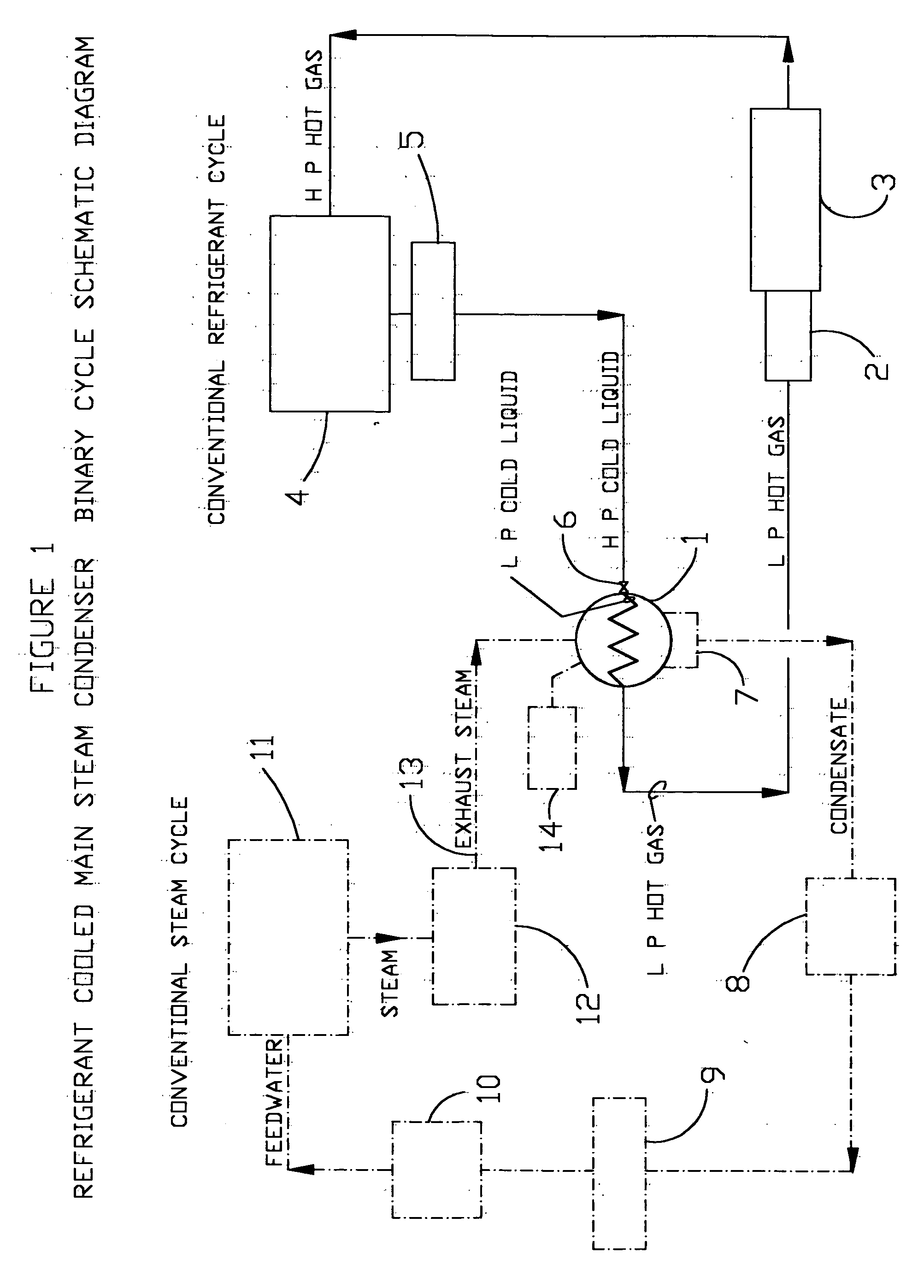
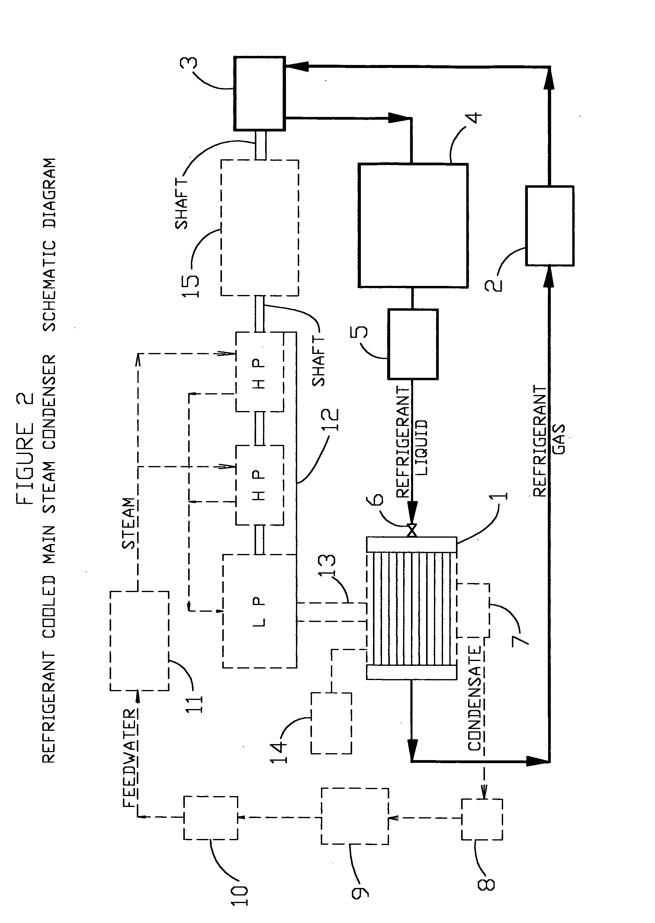
[0008]This invention replaces the main steam condenser cooling water system with a refrigerant cooling system. It should be noted that there is no intent of redesigning the steam cycle or refrigeration cycle. The combining of the steam condenser and the refrigerant evaporator along with the refrigerant compressor being driven by the main steam turbine creates the binary cycle. (FIGS. 1 & 2) The main steam condenser in the modern day power plant is sometimes called the heart of the steam cycle. The differential pressure between the boiler and the condenser causes steam to flow. The lower the internal condenser pressure the more steam flow. The refrigerant low normal temperature and high heat transfer rate lowers the main steam condenser internal pressure much below that of the once thru cooling water system. This increased reduction in the condenser pressure makes the steam cycle much more efficient. This invention is directed toward new plant construction but a maintenance economic ...


PUM


Abstract

This invention reduces the fuel consumption of the modern day power plant by lowering the main steam condenser operating pressure. The main steam condenser is a heat exchanger located in the power plant steam system for condensing steam. The main steam enters the main steam condenser, flowing around the tubes with the coolant flowing thru the tubes, condensing the steam. This invention replaces the present condenser once thru cooling water system with a refrigerant cooling system. The much lower normal temperature and greater high heat absorption rate of the refrigerant, lowers the main steam condenser operating pressure much below that of the present cooling water system. The lower condenser pressure increases steam flow, extracting more energy from the steam, increasing the plant-operating efficiency. This invention combines the conventional steam cycle with the conventional refrigeration cycle. The refrigerant compressor is driven by the main steam turbine which creates the binary cycle.

Description

[0001]The major intent of this invention is to improve the operational efficiency and the functional design of the modern day electrical power generating station. This invention replaces the main steam condenser once through cooling water system with a refrigerant cooling system. The invention is directed primarily toward new power plant construction. Maintenance, equipment replacement cost and future operating cost savings may make it beneficial to convert existing stations. The main steam condenser refrigerant cooling system will reduce fuel consumption with compatible power generation to that of the cooling water system. The intent of this invention is not to redesign the conventional steam cycle or the conventional refrigeration cycle but to combine them. The following drawings will aid in the clarification of this invention:[0002]FIG. 1 is a schematic diagram which shows the conventional steam cycle and the conventional refrigerant cycle crossing at the main steam condenser, wh...

Claims


Application Information

Patent Timeline
IPC IPC(8): F25D23/12F01K9/00F01K9/02
CPCF01K9/003F01K9/02
Inventor BROWN, JOSEPH FRANCIS
Owner BROWN JR JOSEPH FRANCIS
Why Eureka
Try Eureka