Motor ground seal

a technology for bearing isolators and ground seals, which is applied in the direction of mechanical equipment, mechanical energy handling, and repairs, etc., can solve the problems of sealing wear and damage of electrical motors using variable frequency drives, and the inability to obtain adequate maintenance of rotating equipment, so as to prevent leakage of lubricant and the effect of improving the sealing or bearing isolators

Inactive Publication Date: 2007-06-21
INPRO INC
View PDF12 Cites 39 Cited by
  • Summary
  • Abstract
  • Description
  • Claims
  • Application Information

AI Technical Summary

Benefits of technology

[0010] An objective of the present invention is to provide an improvement to seals or bearing isolators to prevent leakage of lubricant and entry of contaminants by encompassing the stator within the rotor to create an axial directed interface at the radial extremity of the rotor. It is also an objective of the present invention to disclose and claim a seal or bearing isolator for rotating equipment that retains lubricants, prevents contamination and conducts and transmits and directs bearing current to ground.

Problems solved by technology

Adequate maintenance of rotating equipment is difficult to obtain because of extreme equipment duty cycles, the lessening of service factors, design and the lack of spare rotating equipment in many processing plants.
Lip seals or O-ring shaft seals can quickly wear out and fail and are also known to permit excessive amounts of moisture and other contaminants to immigrate into the oil reservoir of the operating equipment even before failure had exposed the interface between the rotor and the stator to the contaminants or lubricants at the radial extremity of the seal.
The problem of seal wear and damage as applied to electrical motors using variable frequency drives is compounded because of the very nature of the control of electricity connected to variable frequency drive (hereinafter referred to as VFD) controlled motors.
There are many causes of bearing current including voltage pulse overshoot in the VFD, non-symmetry of the motor's magnetic circuit, supply unbalances, transient conditions, and others.
This random and frequent discharging has an electric discharge machining (EDM) effect, causing pitting of the bearing's rolling elements and raceways.
Over time, this deterioration causes a groove pattern in the bearing race called “fluting” which is a sign that the bearing has sustained severe damage.
Eventually, the deterioration will lead to complete bearing failure.3
Most external applications add to costs, complexity and exposure to external environmental factors.
But, installing insulated bearings does not eliminate the shaft voltage, which will still find the lowest impedance path to ground.
Thus, insulated bearings are not effective if the impedance path is through the driven load.
Therefore, the prior art does not teach an internal, low wearing method or apparatus to efficaciously ground shaft voltage and avoid electric discharge machining of bearings leading to premature bearing failure.

Method used


Image

  • Motor ground seal
  • Motor ground seal
  • Motor ground seal

Examples


Embodiment Construction

—ELEMENT LISTING Description Element No.

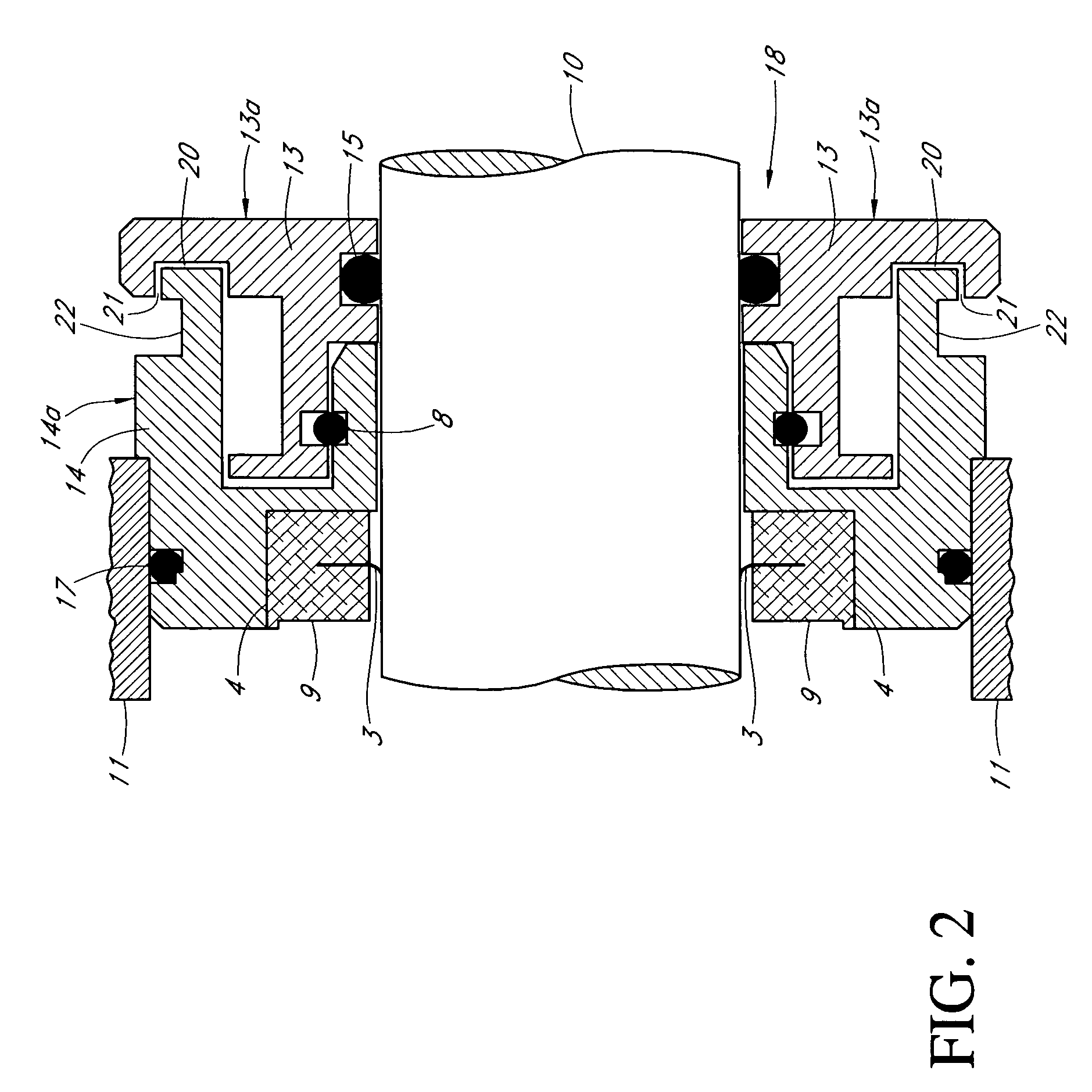
[0031] Intentionally blank 1[0032] Drive bearing 2[0033] Conductive brushes 3[0034] Receptor groove 4[0035] Brush ring 5[0036] Metallic insert with solid conductor ring 6[0037] Conductive insert ring 7[0038] O-ring 8[0039] Solid conductive ring 9[0040] Rotatable shaft 10[0041] Housing 11[0042] Rotatable shaft center 12[0043] Rotor 13[0044] Rotor surface 13a [0045] Stator 14[0046] Stator surface 14a [0047] O-ring 15[0048] Brush ring frame 16[0049] O-ring 17[0050] Motor ground seal assembly 18[0051] Radial projection 19[0052]1st radial Interface gap 20[0053]2nd radial interface gap 21[0054] Stator groove 22

DETAILED DESCRIPTION

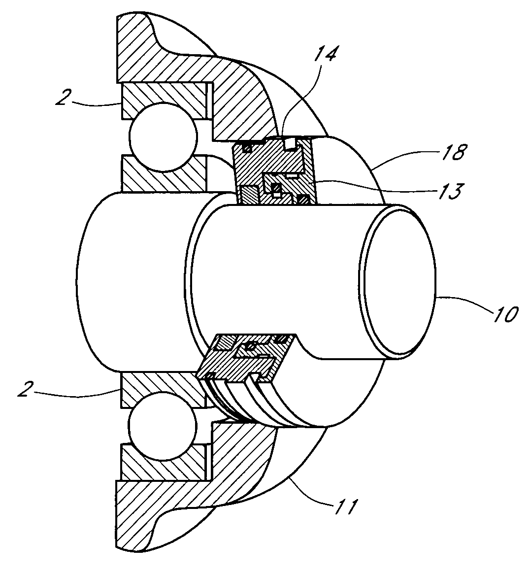
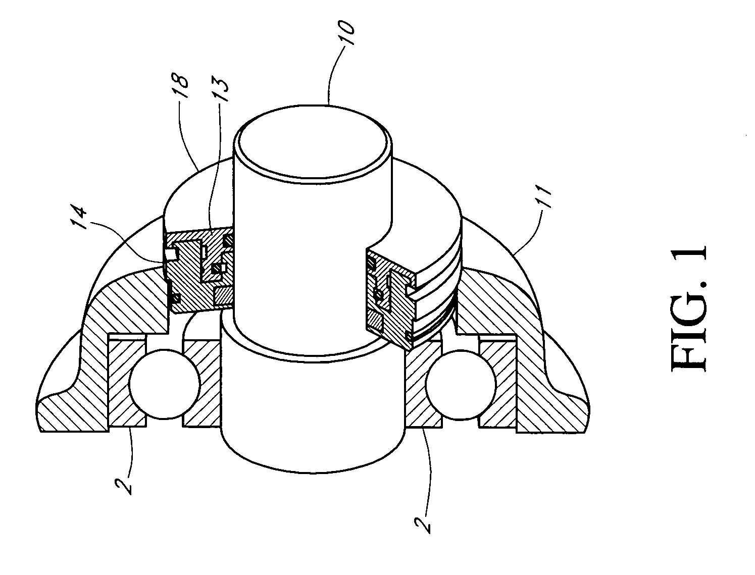
[0055]FIG. 1 illustrates a perspective view of the present invention applied to a rotatable shaft 10 of an electrical motor controller having a variable frequency drive (VFD). (Motor not shown) The motor ground sealtm assembly 18 shown in FIG. 1 may be mounted to rotatable shaft 10 on either one or both sides of the pump h...


PUM

PropertyMeasurementUnit
diameteraaaaaaaaaa
frequencyaaaaaaaaaa
diameteraaaaaaaaaa

Abstract

A shaft seal assembly is disclosed having a stator including a main body and axial and radial projections therefrom. The rotor is radially extended and encompasses the axial and radial projections from said stator. A passageway formed between the radial projection of stator and rotor results in an axial passageway having its opening facing rearwardly from the rotor and away from the source of impinging coolant and/or contaminant. A concentric circumferential receptor groove in the stator facing the housing allows insertion of conductive means for transmission of electrostatic charge away from the shaft through the shaft seal assembly to the housing and ground. The receptor groove is opposite the axial passageway and provides for both a substantially lower contaminant environment and improved engagement with conductive means. The dimension of interface gap between the rotor and the radial projection from the stator, which the access to the shaft of any impinging material is fixed at a predetermined value and does not vary with the relative movement between the rotor and the stator. The shaft seal assembly provides improved rejection or warding off of contaminants from ingress into the labyrinths and ultimately restrains attack of the bearing environment as well as substantial elimination of bearing current and attendant bearing fluting or frosting.

Description

CROSS-REFERENCE TO RELATED APPLICATIONS [0001] The present application claims the benefits of U.S. Provisional Application Serial No. 60 / 693,548, filed Jun. 25, 2005. Applicant herein claims priority from and incorporates herein by reference in its entirety provisional patent application No. 60 / 693,548.STATEMENT REGARDING FEDERALLY SPONSORED RESEARCH OR DEVELOPMENT [0002] No federal funds were used to develop or create the invention disclosed and described in the patent application. FIELD OF THE INVENTION [0003] The present invention relates to an improved bearing isolator sealing device, and more particularly, to a bearing isolator for directing electrostatic charge to ground while retaining lubrication solution and repelling contamination such as water, dust, dirt, sand and paper stock from the bearing environment and away from the shaft grounding ring, within the bearing cavity of a hub assembly such as an electrical motor bearing for engagement with a rotatable shaft. BACKGROUND...

Claims


Application Information

Patent Timeline
Patent Type & Authority Applications(United States)
IPC IPC(8): H02K5/16H05F3/02F16J15/447
CPCF16J15/4478H02K5/10Y10T29/49826F16C33/80H02K11/0089H02K11/40
Inventor ORLOWSKI, DAVID C.COE, THOMAS D.
Owner INPRO INC
Why Eureka
Try Eureka