Fisheye lens unit

a technology of fisheye lens and lens body, which is applied in the field of fisheye lens body, can solve the problems of relativly difficult to reduce the number of lenses for forming the fisheye lens body, and achieve the effect of compact lens body and high performan

Inactive Publication Date: 2007-06-21
ELMO CO LTD
View PDF5 Cites 77 Cited by
  • Summary
  • Abstract
  • Description
  • Claims
  • Application Information

AI Technical Summary

Benefits of technology

[0027] By employing this configuration, it is possible to make the lens unit more compact. It is also possible to obtain a high performance lens unit with little spherical aberration, coma aberration, astigmatism, chromatic aberration of magnification.

Problems solved by technology

Namely, when using the projection methods (3) and (4), it was relatively difficult to make the number of lenses smaller for constituting the fisheye lens unit.

Method used


Image

  • Fisheye lens unit
  • Fisheye lens unit
  • Fisheye lens unit

Examples


first embodiment

A. First Embodiment

A-1. Configuration of Fisheye Lens Unit:

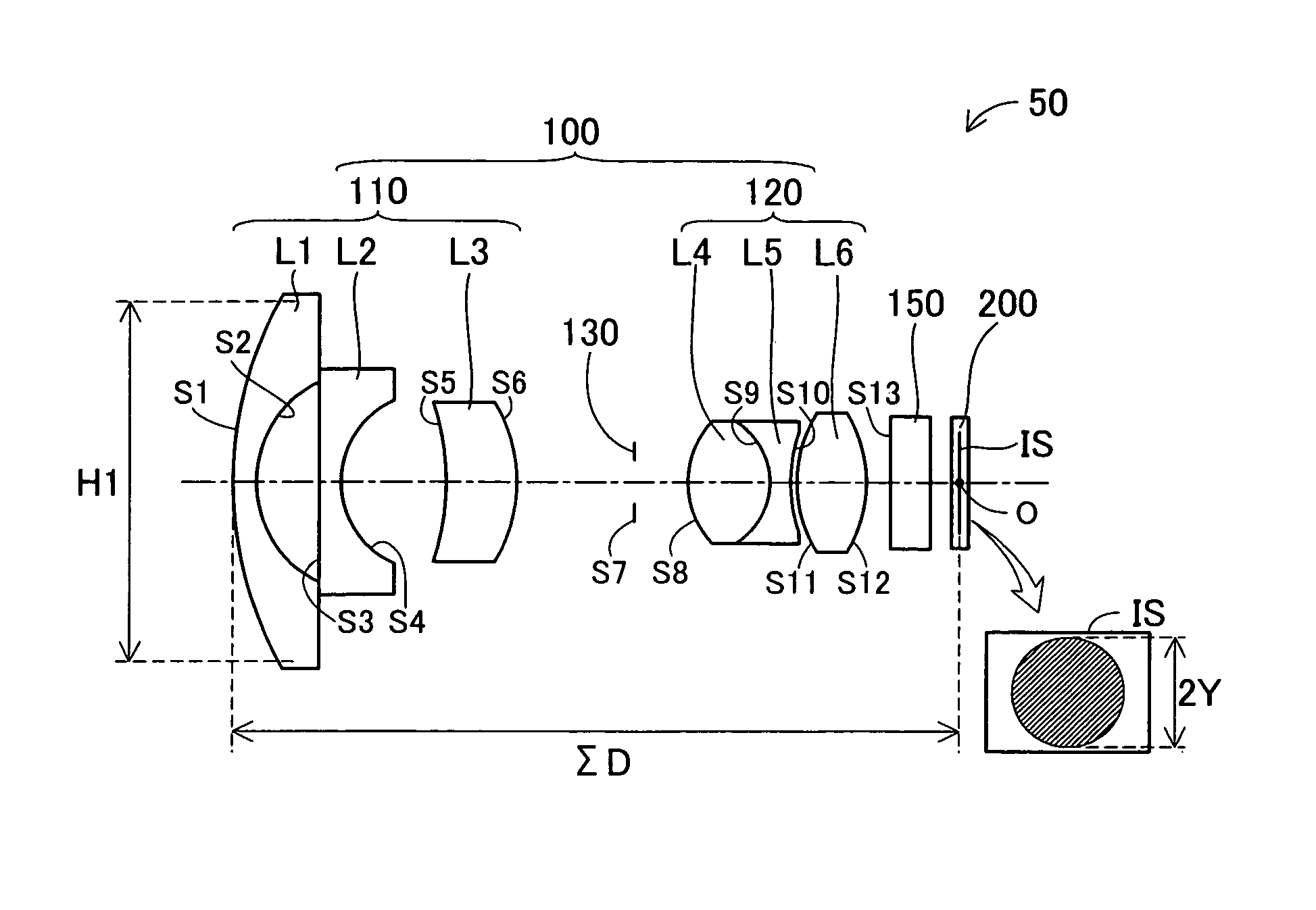
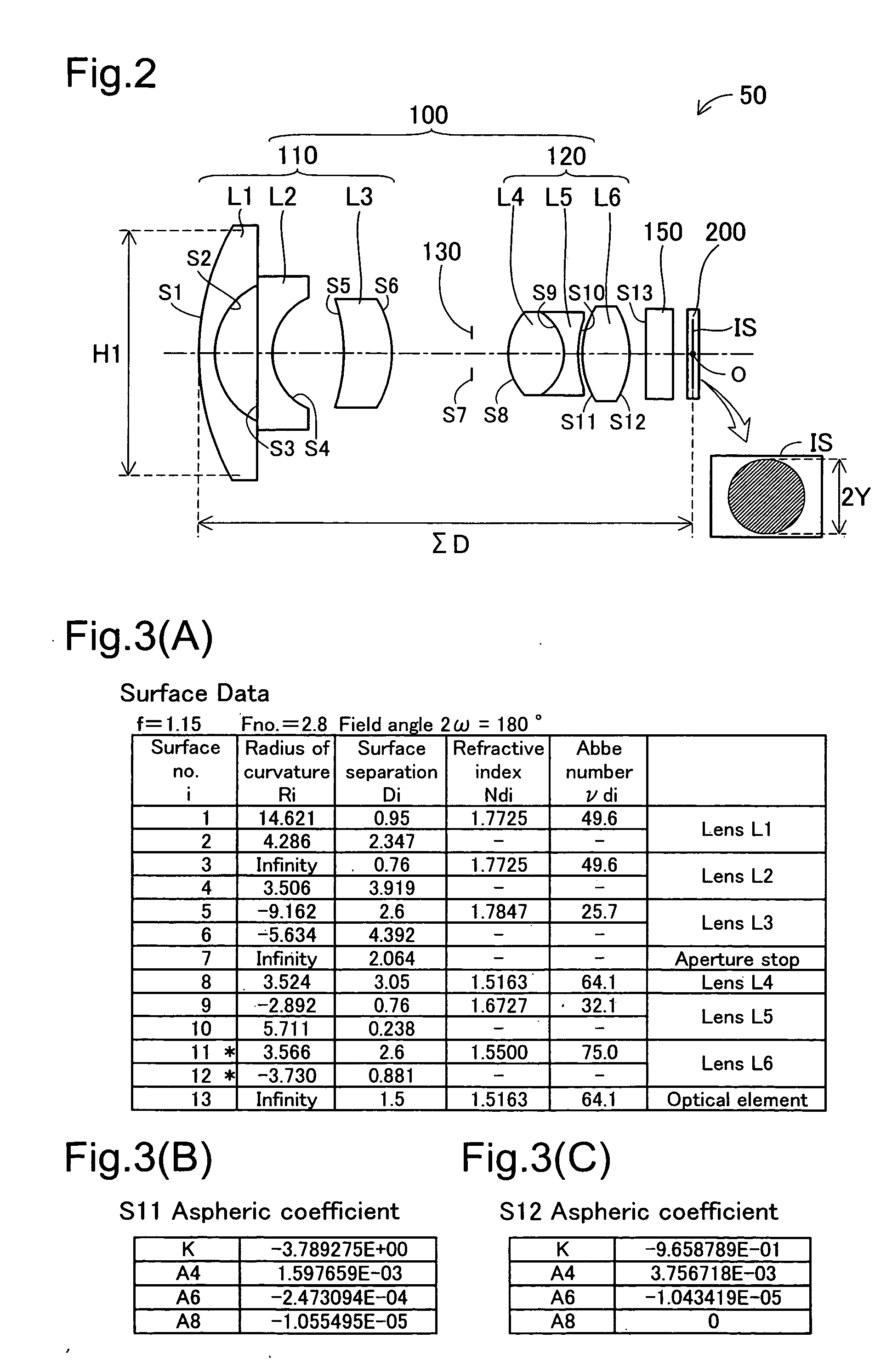
[0060]FIG. 2 shows basic configuration of an imaging apparatus 50 according to the first embodiment. As shown in the drawing, the imaging apparatus 50 includes a fisheye lens unit 100, a solid-state imaging device 200 such as a CCD (charge coupling device), and an optical element 150 provided between the fisheye lens unit 100 and the solid-state imaging device 200. The optical element 150 includes, for example, an optical filter, cover glass of the solid-state imaging device, or the like. The solid-state imaging device 200 has an image surface (imaging surface) IS.

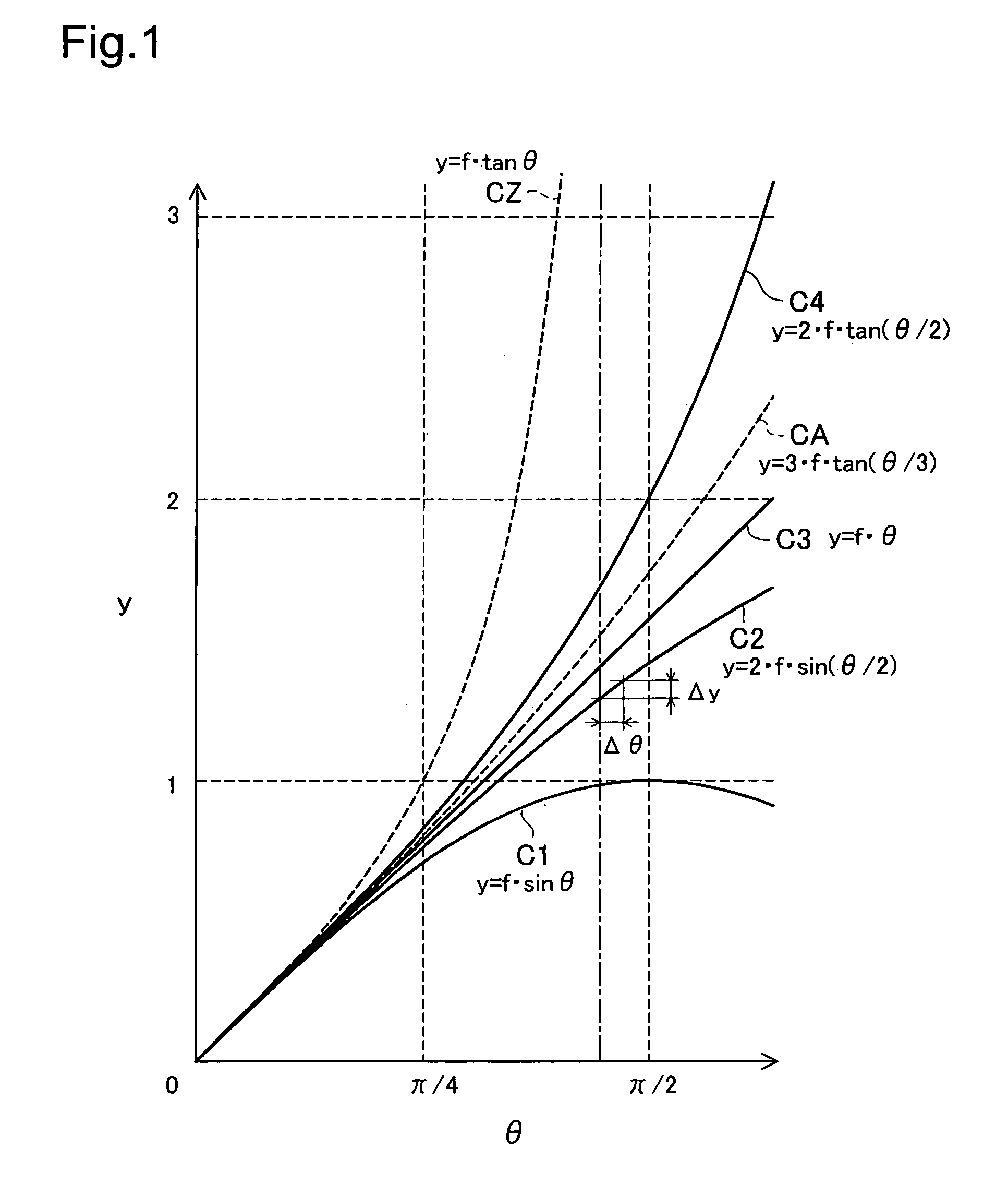
[0061] The fisheye lens unit (also called simply “lens unit” hereafter) 100 includes a plurality of lenses that constitute the fisheye lens. The equidistant projection method represented by y=f·θ (see curve C3 in FIG. 1) is used for the lens unit 100 of this embodiment.

[0062] The lens unit 100 includes a first lens group 110 arranged on the object side, a secon...

second embodiment

B. Second Embodiment

B-1. Configuration of Fisheye Lens Unit:

[0099]FIG. 7 shows basic configuration of an imaging apparatus 50B according to the second embodiment. FIG. 7 is similar to FIG. 2, but the lens unit 100B is modified. In this embodiment, similar to the first embodiment, the equidistant projection method represented by y=f·θ (see curve C3 in FIG. 1) is used for the lens unit 100B.

[0100] The lens unit 100B, similar to the first embodiment, includes a first lens group 110B arranged on the object side, a second lens group 120B arranged on the image side, and an aperture stop 130B arranged between the first lens group 110B and the second lens group 120B.

[0101] The first lens group 110B is constituted by three lenses. The first lens L1 is a concave meniscus lens that has a convex surface on the object side and has a concave surface on the image side. The second lens L2 is a biconcave lens that has concave surfaces on both the object side and the image side. The third lens L3...

third embodiment

C. Third Embodiment

C-1. Configuration of Fisheye Lens Unit:

[0110]FIG. 12 shows basic configuration of an imaging apparatus 50C according to the third embodiment. FIG. 12 is similar to FIG. 2, but the lens unit 100C is modified. In this embodiment, in contrast to the first and second embodiments, the projection method represented by y=3·f·tan(θ / 3) (see curve CA in FIG. 1) is used for the lens unit 100C.

[0111] The lens unit 100C, similar to the first embodiment, includes a first lens group 110C arranged at the object side, a second lens group 120C arranged at the image side, and an aperture stop 130C arranged between the first lens group 110C and the second lens group 120C.

[0112] The first lens group 110C is constituted by four lenses. The first lens L1 is a concave meniscus lens that has a convex surface on the object side and has a concave surface on the image side. The second lens L2 is a plano-concave lens that has a planar surface on the object side and a concave surface on t...


PUM


Abstract

To provide a technique to constitute a fisheye lens unit with a small number of lenses. A fisheye lens unit uses a predetermined projection method, wherein a variation for the predetermined projection method is not less than the variation for an equidistant projection method, the variation being expressed by an increment of an image height in relation to an increment of an incident angle at a predetermined incident angle. The fisheye lens unit includes: a first lens group provided on an object side; a second lens group provided on an image side; and an aperture stop provided between the first lens group and the second lens group. The first lens group consists of three or four lenses, the second lens group consists of two or three lenses including a final lens provided on the furthest image side of the second lens group, and the final lens is an aspheric lens that has an aspheric shape on at least one of two surfaces of the aspheric lens.

Description

CROSS REFERENCE [0001] The present application is based on, and claims priority from, Japanese Application No. 2005-363503 filed Dec. 16, 2005, the disclosure of which is herein incorporated by reference. BACKGROUND [0002] 1. Technical Field [0003] The present invention relates to a fisheye lens unit. [0004] 2. Related Art [0005] Fisheye lens units including a plurality of lenses that constitute a fisheye lens are incorporated on still cameras and monitoring cameras, and are widely used to photograph wide area spaces. [0006] Here, the fisheye lens represents a lens having a field angle of 160 degrees or greater, and normally having a field angle of 180 degrees or greater. The fisheye lens differs from a wide angle lens in that distortion is generated intentionally. [0007] A specified projection method is used for the fisheye lens. For example, the following kinds of projection methods are well known. [0008] (1) Orthogonal projection method - - - y=f·sin θ[0009] (2) Equisolid angle p...

Claims


Application Information

Patent Timeline
Patent Type & Authority Applications(United States)
IPC IPC(8): G02B9/08
CPCG02B13/06
Inventor KAWADA, MAYUMI
Owner ELMO CO LTD
Why Eureka
Try Eureka