Unlock instant, AI-driven research and patent intelligence for your innovation.

Rotating electric machine and manufacturing method thereof

a technology of rotating electric machines and manufacturing methods, which is applied in the direction of electronic commutators, motor/generator/converter stoppers, dynamo-electric converter control, etc., can solve the problems of high manufacturing costs, complicated connection work, and large size of entire devices, and achieve the effect of reducing manufacturing costs

Active Publication Date: 2007-06-21
MITSUBISHI ELECTRIC CORP
View PDF5 Cites 0 Cited by
  • Summary
  • Abstract
  • Description
  • Claims
  • Application Information

AI Technical Summary

Benefits of technology

[0009] The present invention has been to solve the problems as mentioned above, and has an object of downsizing a control device of a rotating electric machine to which an inverter is integrally assembled, as well as reducing manufacturing costs.
[0010] It is a further object of the invention to provide a rotating electric machine in which a heat sink having conductivity is used as a conductor, as well as wirings having different polarities can be insulated from each other in a simple structure.
[0012] According to the rotating electric machine of the invention, it is possible to downsize a control device, as well as to reduce manufacturing costs.

Problems solved by technology

Moreover, the metal board and the control board are connected via the terminals of the connection member, a connection work is complicated, and a space for connecting terminals and boards together is also needed.
Thus, the entire device gets larger, as well as a problem exists in high manufacturing costs.
A large number of parts or the mounting space comes to be a cause of preventing the downsizing.
Therefore, a large amount of heat is transferred to an insulating layer on the metal board, and thus a problem exists in that the metal board and the insulating layer are separated.
In the conventional structures using an expensive metal board or grease, there has to be provided an insulating layer of the board having insulating properties or grease, resulting in larger manufacturing costs of the rotating electric machine.

Method used


Image

  • Rotating electric machine and manufacturing method thereof
  • Rotating electric machine and manufacturing method thereof
  • Rotating electric machine and manufacturing method thereof

Examples


embodiment 1

[0022]FIG. 1 is a sectional side view showing a rotating electric machine to which an inverter is integrally assembled according to a first embodiment of the invention.

[0023] With reference to the drawing, a rotating electric machine 1 is provided with a case formed of a front bracket (not shown) and a rear bracket 2; a shaft 4 rotatably supported via bearings 3 with respect to the case; a rotor 6 that is fixed to this shaft 4, and includes a field winding 5; a stator 7 that is fixed to the case, as well as disposed so as to surround the rotor 6, and further includes an armature winding 7a; fans 8 fixed to two end faces in the axial direction of the rotor 6; a pulley 9 fixed to an end portion of the front side of the shaft 4; a brush holder 10 attached to the rear bracket 2 so as to be located at the perimeter of the rear side of the shaft 4; a pair of slip rings 11 mounted onto the rear side of the shaft 4; a pair of brushes 12 disposed in the brush holder 10 so as to slide in con...

embodiment 2

[0061]FIG. 5 is a side view showing a state that a lower arm 33 and upper arm 31 of U-phase are assembled.

[0062] The lower arm 33 and the upper arm 31 are assembled in the state that the switching elements 16 are opposed. A metal pattern 42 to which a source electrode terminal 16b of the upper arm 31 is joined is extended to a heat sink 17b of the lower arm 33, and the metal pattern 42 is fixed to the heat sink 17b with a screw 51.

[0063] Owing to such construction, the drain electrode terminal 16a of the lower arm 33 and the source electrode terminal 16b of the upper arm 31 are electrically connected. thus, the switching element 16 of the upper arm 31 and the switching element 16 of the lower arm 33 comes to be connected in series.

[0064] Furthermore, to suppress the variation of the DC power source, and to smooth, e.g., the rise of voltage, a smoothing capacitor 52 is used. The smoothing capacitor 52 is joined at the portion exposed outside a resin covering a metal pattern 42 for...

embodiment 3

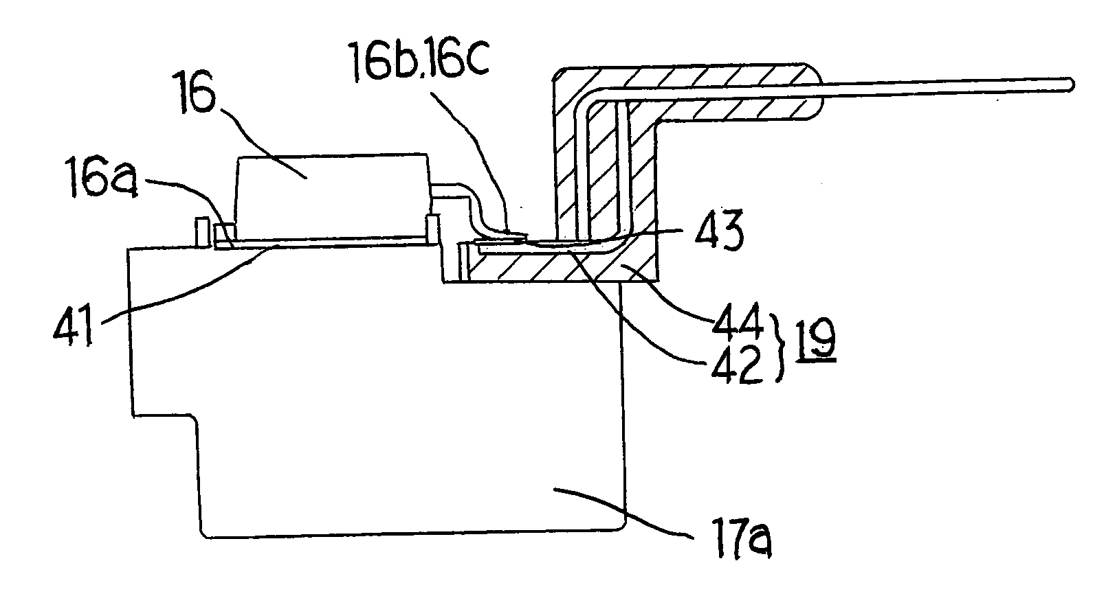
[0068]FIG. 6 is a plan view showing a lower arm portion of U-phase. With reference to the drawing, drain electrode terminals 16a of a plurality of switching elements 16 are joined to the same heat sink 17b with solders 41. Source electrode terminals 16b and gate electrode terminals 16c are joined to respective metal patterns 42 with solders 43. In this manner, a plurality of switching elements 16 are joined to one connection member 19 in the state of being close to each other, so that they can be connected to the control board 18 via one output terminal. Consequently, it is possible to be unaffected by noises, and further to downsize the entire device.


PUM


Abstract

A control device of a rotating electric machine to which an inverter is integrally assembled is downsized, and manufacturing costs are reduced. An inverter for controlling outputs from the rotating electric machine is integrated with a rotating electric machine, and in which a control device forming an inverter is constructed of a switching element and a heat sink, a drain electrode terminal of the switching element is directly joined to the heat sink, and a source electrode terminal and gate electrode terminal of the switching element are joined to a metal pattern formed at a connection member.

Description

BACKGROUND OF THE INVENTION [0001] 1. Field of the Invention [0002] The present invention relates to a rotating electric machine to which an inverter is integrally assembled and, more particularly, to a rotating electric machine that contains therein a control device to be installed on electric vehicles, hybrid vehicles, and idle-stop vehicles. The invention also relates to a manufacturing method of the rotating electric machine. [0003] 2. Description of the Related Art [0004] In conventional rotating electric machines to which an inverter is integrally assembled, there is the one in which switching elements are mounted on a metal board, being an aluminum substrate on which a metal pattern is formed via an insulating layer. Further, to make an electrical connection between the metal board and a control board, there is provided a connection member formed by enveloped casting of the metal pattern with resin. One of connection terminals of the connection member is connected to a land s...

Claims


Application Information

Patent Timeline
Patent Type & Authority Applications(United States)
IPC IPC(8): H01G2/08
CPCH02K11/0073H02K11/046H02K11/33H02K11/05
Inventor YOSHIHARA, HIROYUKIKIKUCHI, MASAOKATO, MASAKIASAO, YOSHIHITO
Owner MITSUBISHI ELECTRIC CORP