Method and apparatus for implementing beam forming in cdma communication system

a beamforming and communication system technology, applied in the field of mobile communication, can solve the problems of limiting the capacity of the cdma system, generating pilot frequency pollution, complicated system realization, etc., and achieve the effect of capacity and performan

Inactive Publication Date: 2007-06-21
ZTE CORP
View PDF6 Cites 49 Cited by
  • Summary
  • Abstract
  • Description
  • Claims
  • Application Information

AI Technical Summary

Benefits of technology

[0016] The purpose of the present invention is to provide a device for realizing beam-forming in CDMA system and method thereof, in which the smart antenna technique is used to form multiple fixed beams in a sector in CDMA system, and multiple fixed beams are used in the same smart antenna system to form traffic channels with narrow beams and common channels with sector beams (such as the pilot channel, the paging channel and the synchronization channel) simultaneously, and the problem of phrase inconsistency of each channel due to the variations of time and temperature is conquered without complicated correction technique, therefore the capacity and performance of CDMA system with multiple antennas are improved. The CDMA system herein comprises but does not limit to such code division multiple access systems as CDMA95, CDMA2000, WCDMA, MC-CDMA and TD-SCDMA systems, all of which use the principle of spreading spectrum.
[0021] said optical transceiver system, including an optical fiber, an optical interface board close to the base band system and an optical interface board close to the transceiver system, enables the base band system to be placed in the warehouse so as to make the base band system support more sectors, and the radio frequency part close to the antennas, and thereby reduce the power loss;
[0028] said optical transceiver system, transceiver system, analog fixed beam-forming network, antenna system and radio frequency links therebetween can be placed on tower or holding pole, so as to make the radio frequency cables therebetween as short as possible and easy to correct, thereby the loss of output power of the power amplifier is reduced, and the coverage area is increased;
[0034] said optical transceiver system, including an optical fiber and an optical interface board close to the base band system and an optical interface board close to the transceiver system, enables the base band system to be placed in the warehouse so as to make the base band system support more sectors, and the radio frequency part close to the antenna, thereby reduce the power loss;
[0058] when transmitting the common information, the beams at the end at the antennas are made to have different time delays so that they will not correlate with one another when forming the common channel beams, thereby, the problem that the fixed beams in some area correlate with and counteract one another when composing the beams covering the whole sectors is avoided.
[0059] The device and method of the present invention solves the problem that the fixed beams in some area correlate with and counteract one another or are greatly reduced due to the correlating addition of the space vectors of each fixed beam when the multiple antenna CDMA system transmits the common channels, and makes the strength of the pilot channel and the traffic channel in corresponding proportion in the coverage area. Compared with prior art, the present invention simplifies the equipment, algorithm and design of the correction schemes, and improves the signal to noise ratio of receiving signals by the mobile station. The adding of an optical transceiver system between the base band and the radio frequency TRX aims to draw the TRX as well as the other radio frequency systems close to the antennas through the optical fiber, so as to enable the base band system to be placed in warehouse (indoor), the base band to support more sectors, the radio frequency to be placed near to the antennas and the power consumption to be reduced.

Problems solved by technology

However, because users of CDMA system share one single wideband channel, the common channel interference (CCI) among respective users will be resulted, which limits the capacity of the CDMA system.
On the respects of lowering the interference of the system and improving the capacity,t he method commonly used is to use the technique of sectoring the cell, too many of sectors, however, will bring about too much handoff load to the system, and will generate pilot frequency pollution, therefore, the existing base station equipments commonly employ there or six sectors.
Though it has great flexibility and has good performance gains, the system is complicated in realization, and is very difficult to be updated to the smart antenna system based on the existing system.
When adding the vectors of each beam together to form the pilot channel, the overlays between beams will result in bad addition in some area, and the so-called coverage blind area, where when the mobile stations enter, the talking quality will be decreased greatly, and the call will be even disconnected.
However, this method needs additional high power radio frequency elements and transmission antennas, which will increase the realization cost of the system.
In addition, because the pilot channels and the traffic channels pass different radio frequency links in this method, a complicated correction technique will be needed to overcome the problem of time and phrase offsets of the pilot channels and the traffic channels due to the variations of time and temperature.

Method used


Image

  • Method and apparatus for implementing beam forming in cdma communication system
  • Method and apparatus for implementing beam forming in cdma communication system
  • Method and apparatus for implementing beam forming in cdma communication system

Examples


Embodiment Construction

[0066] The devices and method of the present invention are realized according to the following schemes respectively: [0067] The device of smart antenna beam-forming used in CDMA system is as follows: [0068] The fixed beam-forming network can employ either the digital beam-forming technique, or the analog beam-forming technique. Therefore, according to the different techniques for forming beams, the device of smart antenna fixed beam-forming used in CDMA system can be divided into analog beam-forming device and digital beam-forming device.

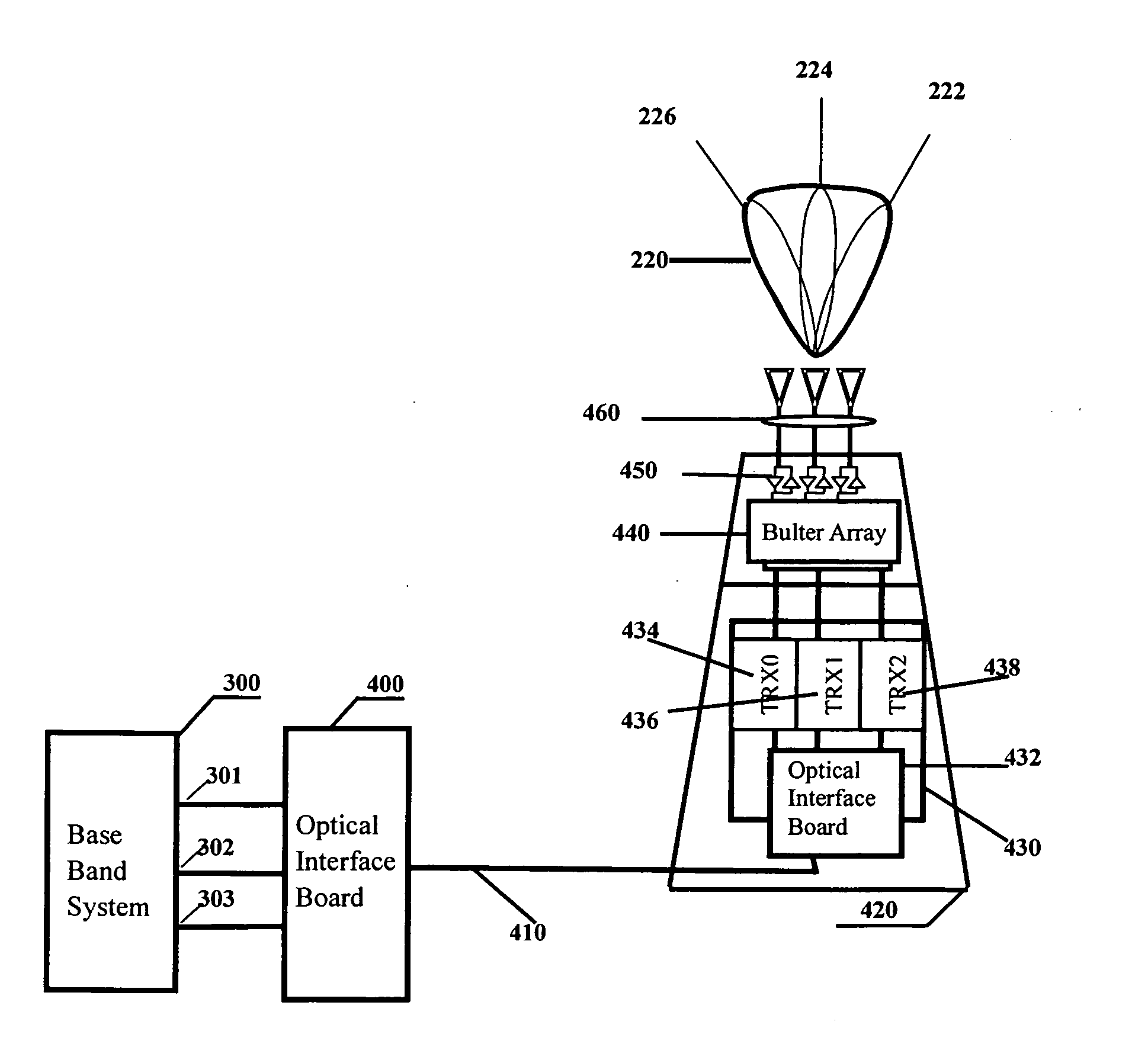
[0069] In which, the device of smart antenna analog fixed beam-forming used in CDMA system comprises in a forward signal flow, at least a base band system, an optical transceiver system, a transceiver (TRX) system, an analog fixed beam-forming network (such as Butler array), a power amplifier, a radio frequency front end (transmission filter) and an antenna system. And according to the signal flow in reverse direction, it at least includes an anten...


PUM


Abstract

The present invention relates to a device for realizing beam-forming in CDMA mobile telecommunication system by employing smart antenna technique and method thereof, which forms multiple fixed beams in a sector, and uses multiple fixed beams to form the traffic channel with narrow beams and the common channel with sector beams simultaneously in the same smart antenna system, and overcomes the problem of inconsistency of phrases of respective channels due to the variations of time and temperature without complicated correction technique, thereby improving the capacity and performance of CDMA system with multiple antennas. It solves the problem that the fixed beams in some area correlate with and counteract one another or are greatly reduced due to the correlating addition of the space vectors of each fixed beam when the multiple antenna CDMA system transmits the common channels, and makes the strength of the pilot channel and the traffic channel in corresponding proportion in the coverage area, and improves the signal to noise ratio of receiving signals by the mobile station. By adding an optical transceiver system between the base band and the radio frequency TRX, the base band part can support more sectors. The radio frequency part is very close to the antennas, therefore the power consumption is reduced.

Description

TECHNICAL FIELD OF THE INVENTION [0001] The present invention belongs to the field of mobile communication, and relates to a device for realizing beam-forming in CDMA system and method thereof, Specifically, to a device for realizing beam-forming by using smart antenna technique in CDMA mobile communication. BACKGROUND OF THE INVENTION [0002] In recent years, CDMA mobile communication system has been developed greatly and employed widely, whose most typical examples are CDMA95, CDMA2000 mobile communication systems commonly used currently in commerce. Compared with mobile communication systems with other mechanisms (such as the time division multiple access TDMA system, the frequency division multiple access FDMA system), the CDMA system has advantages in capacity and service quality. However, because users of CDMA system share one single wideband channel, the common channel interference (CCI) among respective users will be resulted, which limits the capacity of the CDMA system. Fur...

Claims


Application Information

Patent Timeline
Patent Type & Authority Applications(United States)
IPC IPC(8): H04B7/216H01Q1/00H01Q1/24H04B7/00H04B7/04H04B7/06H04B7/08
CPCH01Q1/246H04B7/0408H04B7/0695H04B7/088Y02D30/70
Inventor LI, LILINXIANG, JIYINGWU, YANWEI
Owner ZTE CORP
Why Eureka
Try Eureka