Seal device and method for operating the same and substrate processing apparatus comprising a vacuum chamber

a technology of sealing device and vacuum chamber, which is applied in the direction of engine sealing, thin material processing, basic electric elements, etc., can solve the problems of foreign matter contained in the second space b, 2/b> and may become mixed in the gas flow, so as to avoid the risk of contamination of a space, reduce the time required for reproducing a vacuum, and high cleanliness

Inactive Publication Date: 2007-06-21
EBARA CORP
View PDF4 Cites 17 Cited by
  • Summary
  • Abstract
  • Description
  • Claims
  • Application Information

AI Technical Summary

Benefits of technology

[0051] It is an object of the present invention to provide a seal device, which avoids the risk of contamination of a space required to have high cleanliness and deposition of water on an inner wall surface of the space, and which is capable of reducing a time required for reproducing a vacuum. It is another object of the present invention to provide a method for operating the seal device.
[0052] It is a further object of the present invention to provide a substrate processing apparatus comprising a first vacuum chamber in which a substrate loaded on a stage device is processed and a second vacuum chamber in which a drive device for driving the stage device is provided, wherein the pressure in the second vacuum chamber is controlled to be lower than that in the first vacuum chamber, to thereby solve the above-mentioned problems.
[0053] It is a further object of the present invention to provide a substrate processing apparatus comprising a first chamber in which a substrate loaded on a stage device is processed and a second chamber in which a drive device for driving the stage device is provided, wherein the first chamber is maintained in a vacuum and a non-contacting seal device is provided between the first chamber and the second chamber, and respective pressures in the first and second chambers are controlled in relation to an operating condition of the non-contacting seal device, to thereby solve the above-mentioned problems.

Problems solved by technology

However, pressure conditions of the apparatus are subject to change at a time of starting or stopping the seal device or after stopping the seal device, depending on the method employed for operating the seal device.
From the viewpoint of a time required for starting the individual apparatus, a risk of contamination when stopping the apparatus and maintaining a desired degree of cleanliness, it is necessary to take into account a way in which the apparatus is affected by the method for operating the seal device.
However, the following problems may arise, depending on the method used for starting the seal device.
During the starting operation, there is a possibility that foreign matter contained in the second space 2 may become mixed in the gas flow and clog the small gap in the sealing passage 3.
When use is made of a turbomolecular pump, of which turbine blades are rotated at ultrahigh speed and strike molecules, an excessive amount of external force acts on the blades, thus resulting in the possibility of breakage of the blades.
In other words, it is difficult to achieve the degree of vacuum for which the apparatus is set, and therefore the time for restarting the apparatus is markedly prolonged.
In other words, it is difficult to achieve the degree of vacuum for which the apparatus is set, and therefore a time for restarting the apparatus is markedly prolonged.
However, the use of a rotary motor in combination with a magnetic fluid seal has a demerit such that (a) the life of the magnetic fluid seal becomes short.
That is, the higher the degree of vacuum created in the vacuum chamber, the shorter the life of the magnetic fluid seal.
Thus, it is not possible to effect a smooth linear motion due to rattling or friction of the converting mechanism.
However, there is no vacuum seal suitable for use with a linear motor.
However, the problems of a release of gas and generation of heat cannot be completely avoided in practice.
However, a reaction force and vibrations produced by expansion and contraction of the bellows interfere with a smooth movement of a substrate.
Therefore, a bellows made of a flexible material such as a fluorine resin cannot be used, and effects of a reaction force and vibrations produced by a bellows cannot be avoided.
Theoretically, it is impossible to prevent generation of dust in the rolling mechanism 14.
Consequently, a considerable amount of time is required for reproducing a vacuum.
However, leakage of gas inevitably occurs between two chambers having different pressures.
Further, in practice, there is a problem of a reverse flow or diffusion of gas derived from an oil component from an oil-sealed rotary vacuum pump, an oil component remaining in parts or ducts of a vacuum system, and a lubricant used for the vacuum pump.
However, this leads to a problem, such as a large weight of the apparatus.
Therefore, a problem occurs, such that orthogonality of the movable base 33 of the stage device 31 is impaired, or the substrate's surface is vertically displaced.
It is most undesirable to allow a reverse flow or diffusion of gas derived from an oil component from an oil-sealed rotary vacuum pump, an oil component remaining in parts or ducts of a vacuum system, and a lubricant used for the vacuum pump.

Method used


Image

  • Seal device and method for operating the same and substrate processing apparatus comprising a vacuum chamber
  • Seal device and method for operating the same and substrate processing apparatus comprising a vacuum chamber
  • Seal device and method for operating the same and substrate processing apparatus comprising a vacuum chamber

Examples


Embodiment Construction

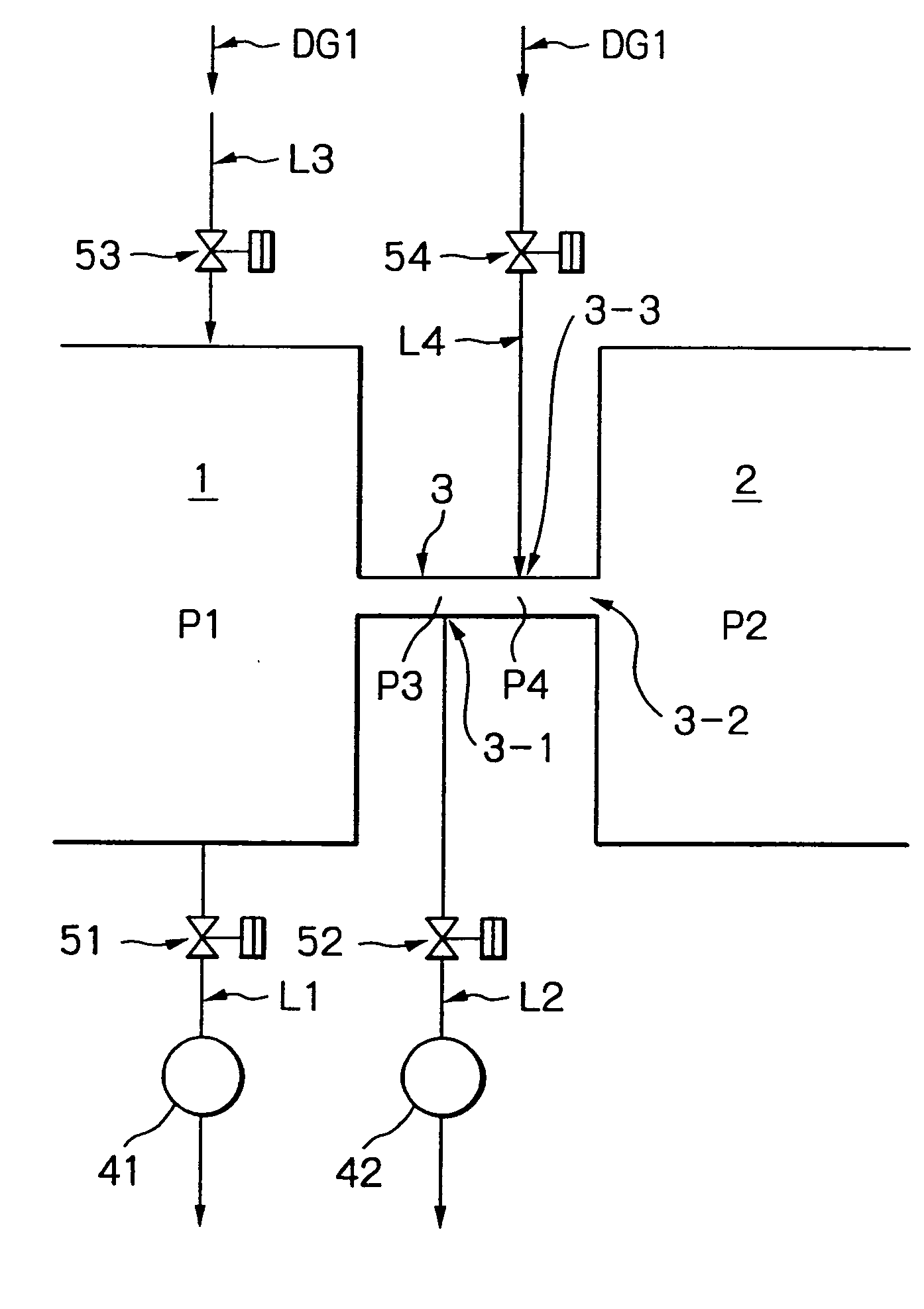
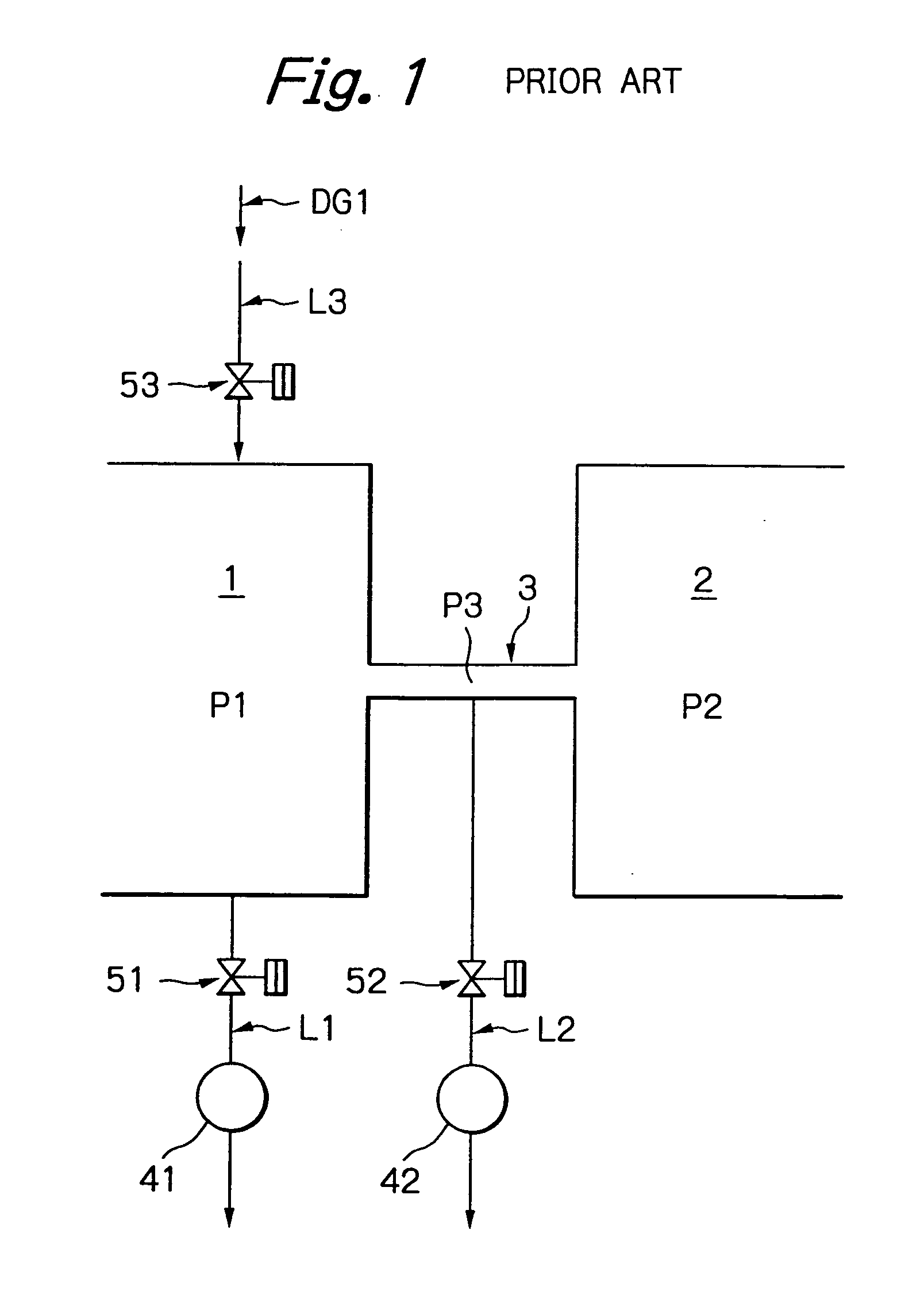
[0097] Hereinbelow, embodiments of the present invention are explained, with reference to FIGS. 10 to 15. As has been described, the problems arising at the time of starting the seal device are such that: (1) a gas occupying the second space 2, which has a lower degree of cleanliness than the first space 1, flows into the first space 1, resulting in a lowering of cleanliness of the first space 1; (2) due to a high humidity of the gas flowing from the second space 2, water is deposited on an inner surface of a wall defining the first space 1, thus lowering the ultimate degree of vacuum in the first space 1; and (3) foreign matter enters a narrow gap in the sealing passage 3, and clogs the sealing passage 3.

[0098]FIG. 10 is a diagram showing a principle of a seal device of the present invention. This seal device is the same as the seal device shown in FIG. 1, in that the sealing passage 3 is provided between the first space 1 and the second space 2, the evacuation line L1 provided wi...


PUM


Abstract

The present invention provides a seal device comprising a sealing passage which allows communication between a first space and a second space, and evacuation lines individually connected to the first space and the sealing passage. A gas feed line for feeding dry gas is connected to the sealing passage.

Description

CROSS-REFERENCE TO RELATED APPLICATIONS [0001] This application is a divisional of U.S. patent application Ser. No. 10 / 404,065, filed on Apr. 2, 2003, the entire contents of which are incorporated herein by reference.BACKGROUND OF THE INVENTION [0002] The present invention relates to a seal device for providing a seal between two spaces having different pressures, and to a method for operating the same, and also relates to a substrate processing apparatus comprising a vacuum chamber. More specifically, the present invention relates to a non-contacting seal device capable of providing a suitable seal in a semiconductor manufacturing apparatus between two spaces having different pressures and method for operating the same, and also relates to a substrate processing apparatus comprising a vacuum chamber in which a stage device is provided, wherein a substrate for producing a semiconductor or a liquid crystal is loaded on the stage device and processed in the vacuum chamber. In the subs...

Claims


Application Information

Patent Timeline
Patent Type & Authority Applications(United States)
IPC IPC(8): H01L21/677F16J15/40H01L21/00
CPCF16J15/406H01L21/67126Y10S414/141Y10S414/135Y10S414/139
Inventor SHINOZAKI, HIROYUKI
Owner EBARA CORP
Why Eureka
Try Eureka