Wind power plant of cyclone type and method of obtaining energy from such

Inactive Publication Date: 2007-06-21
KARIN OLDIN +1
View PDF7 Cites 2 Cited by
  • Summary
  • Abstract
  • Description
  • Claims
  • Application Information

AI Technical Summary

Benefits of technology

[0004] A purpose of the invention is to improve the power-generation of wind power plants of the mentioned kind in a way that results in a low investment cost as well as high reliability and low costs of maintenance.
[0007] By designing the tower to have a non-circular elliptical shape with the large axis of the ellipse arranged to be parallel to the direction of the incoming wind as viewed in a horizontal plane, the power-extraction is increased. This is due to the fact that the laminar flow changes direction and speed several times for each rotation of its whirlwind movement and each retardation and acceleration results in kinetic energy being transformed into heat energy whereby the rise velocity in the tower is increased. A thermal formation is achieved in a very simple and efficient manner.

Problems solved by technology

The plates give rise to a disturbance in the airflow by causing turbulence.
A very complicated and expensive device is proposed.

Method used


Image

  • Wind power plant of cyclone type and method of obtaining energy from such
  • Wind power plant of cyclone type and method of obtaining energy from such
  • Wind power plant of cyclone type and method of obtaining energy from such

Examples


Embodiment Construction

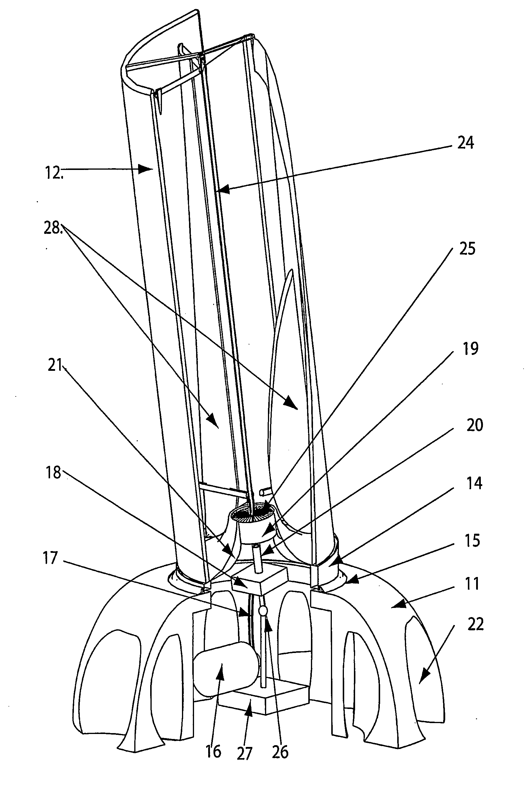
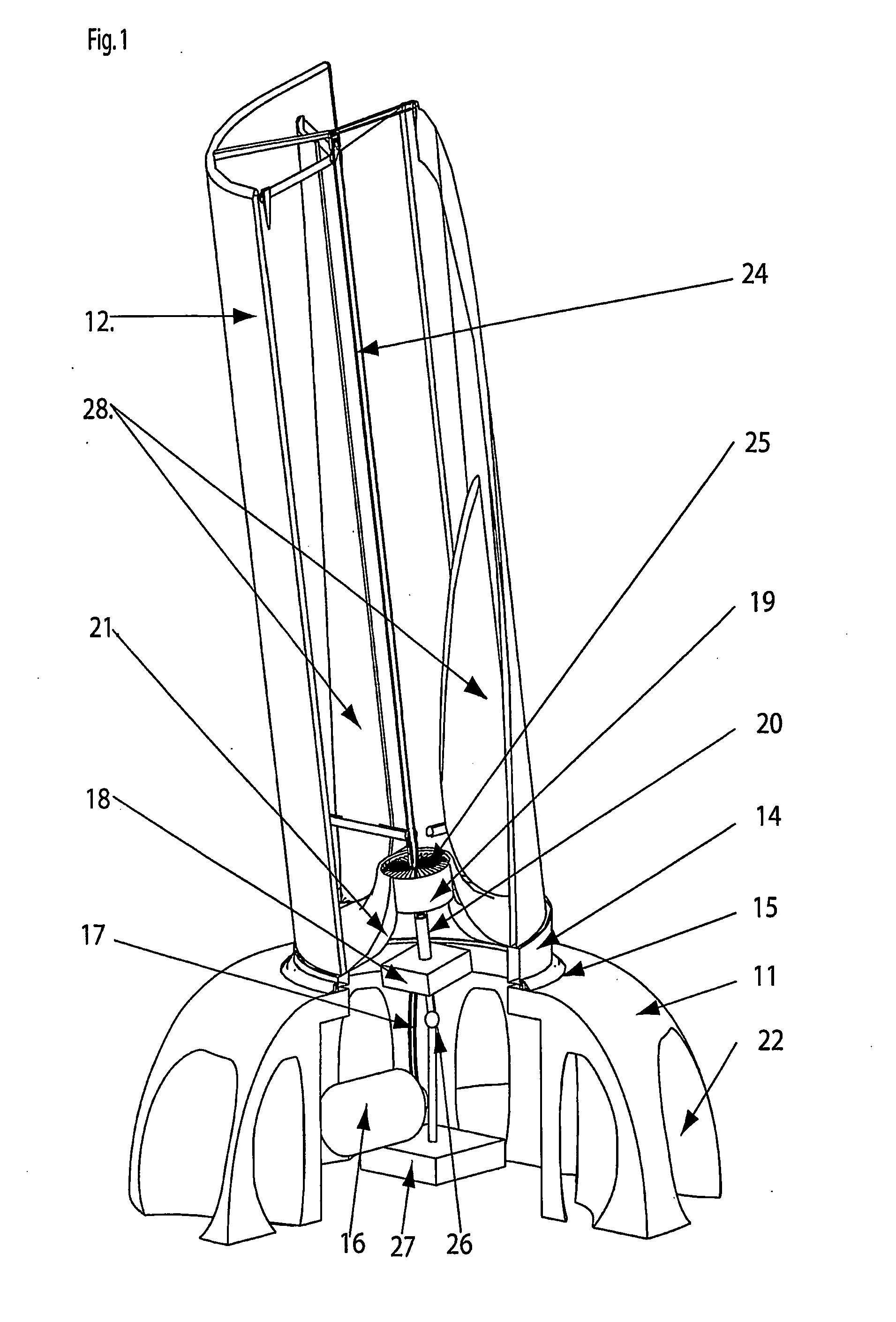
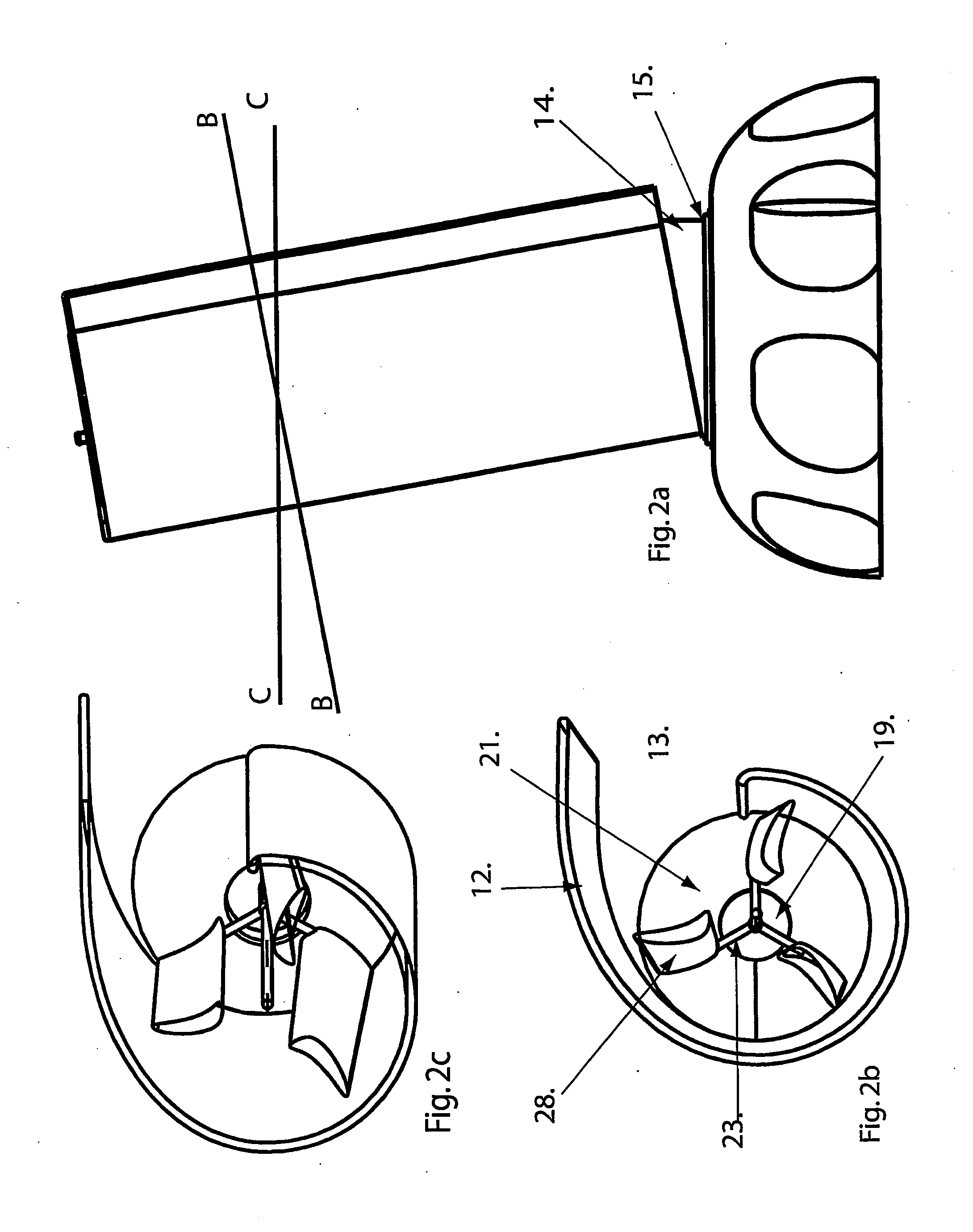
[0016] In FIGS. 1-3, a wind power plant having a base 11 and a rotatable tower 12 mounted onto the base is shown. The tower 12 has a circular cross section (see b-b in FIG. 2a) and a wind inlet 13 as illustrated in FIG. 2b. The wind inlet extends along the entire height of the tower. The lower portion of the tower is provided with a wedge 14, which makes the tower lean away from the wind and this wedge is horizontally mounted in a bearing 15 in the upper portion of the base and the rotation of the tower is driven by a motor (not shown) and the control is automatic so that the wind inlet is always facing the wind. The tower is hence rotated around the vertical axis of the bearing 15.

[0017] Inside the base there is a generator 16 built together with a hydraulic motor, which is driven by a hydraulic pump 18 via hydraulic hoses 17. A substantially horizontal turbine 19 in the lower portion of the tower drives the hydraulic pump 18 via a hollow axis, a tubular shaft 20, which is paralle...


PUM


Abstract

A wind power plant having a tower (12) open at the top and provided with a side inlet (13) for the wind for generating a cyclone in the tower and a substantially horizontal turbine (19) that has inlets (21, 22) through the base and outlet to the center of the cyclone in the tower and that is driving a generator (16). The tower is rotatable and has a non-circular elliptical shape viewed in the horizontal plane. This shape increases the power of the wind power plant as compared to a tower with a circular shape. During operation the tower is turned so that the wind inlet is always facing the wind.

Description

TECHNICAL FIELD OF THE INVENTION [0001] The present invention relates to a method of obtaining energy from a wind power plant comprising a tower with a generator-driving turbine, the axis of which is parallel and coaxial to the tower, whereby a cyclone is generated in the open-ended tower with a side inlet for the wind, so that the low-pressure region in the center of the cyclone generates the driving power for the air flow through the turbine. [0002] The invention also relates to a wind power plant of cyclone type comprising a base, an open-ended tower arranged above the base and being provided with a side inlet for the wind to generate a cyclone in the tower, a turbine having its axis parallel to the tower and inlet(s) through the base and outlet(s) to the center of the cyclone in the tower and being connected to drive a generator arranged in the base. BRIEF DESCRIPTION OF THE PRIOR ART [0003] A wind power plant of the above-mentioned type is known from U.S. Pat. No. 4,935,639 A, ...

Claims


Application Information

Patent Timeline
IPC IPC(8): F03D7/06F03D3/00
CPCF03D3/005F05B2240/132Y02E10/74
Inventor STIIG, ERICGOLRIZ, MOHAMMAD R.
Owner KARIN OLDIN
Why Eureka
Try Eureka