Flexible electrode array for artificial vision

a flexible electrode array and artificial vision technology, applied in the field of electrodes, can solve the problems of inability to apply the knowledge in the long-term, unfavorable, and difficult selection of appropriate nerve fibers to stimulate to produce formed vision,

Inactive Publication Date: 2007-06-21
LAWRENCE LIVERMORE NAT SECURITY LLC +1
View PDF16 Cites 61 Cited by
  • Summary
  • Abstract
  • Description
  • Claims
  • Application Information

AI Technical Summary

Problems solved by technology

Practical long-term application of this knowledge, however, was not possible until the relatively recent development of totally implantable miniature electronic circuits which avoid the risk of infection at the sites of percutaneous connecting wires.
The success of this device is unlikely due to it having to duplicate the complex frequency modulated neural signals of the nerve fiber layer.
Selection of appropriate nerve fibers to stimulate to produce formed vision would be extremely difficult, if not impossible.
However, because that device had no discrete surface structure to restrict the directional flow of charges, lateral migration and diffusion of charges would occur thereby preventing any acceptable resolution capability.
Placement of that device between the sclera and choroid would also result in blockage of discrete ion migration to the photoreceptor and inner retinal layers.
As that device would be inserted into or through the highly vascular choroid of the posterior pole, subchoroidal; intraretinal and intraorbital hemorrhage would likely result along with disruption of blood flow to the posterior pole.
Even with fenestrations of various geometries, permeation of oxygen and biological substances was not optimal.
The ability of these devices to function in continuous low light environments was, therefore, limited.
Alignment of ISEMCPs and ISEMCP-Cs in the subretinal space so that they would all face incident light was also difficult.”

Method used


Image

  • Flexible electrode array for artificial vision
  • Flexible electrode array for artificial vision
  • Flexible electrode array for artificial vision

Examples


Embodiment Construction

[0029] Referring now to the drawings, to the following detailed information, and to incorporated materials; a detailed description of the invention, including specific embodiments, is presented. The detailed description serves to explain the principles of the invention. The invention is susceptible to modifications and alternative forms. The invention is not limited to the particular forms disclosed. The invention covers all modifications, equivalents, and alternatives falling within the spirit and scope of the invention as defined by the claims.

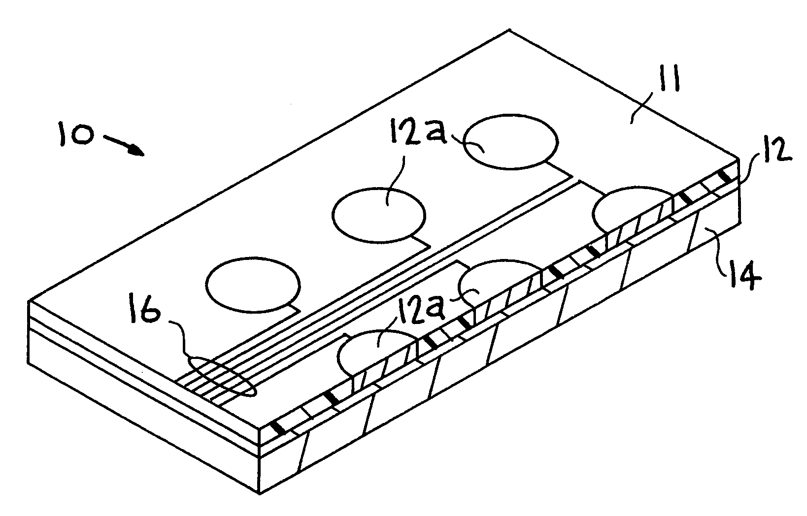
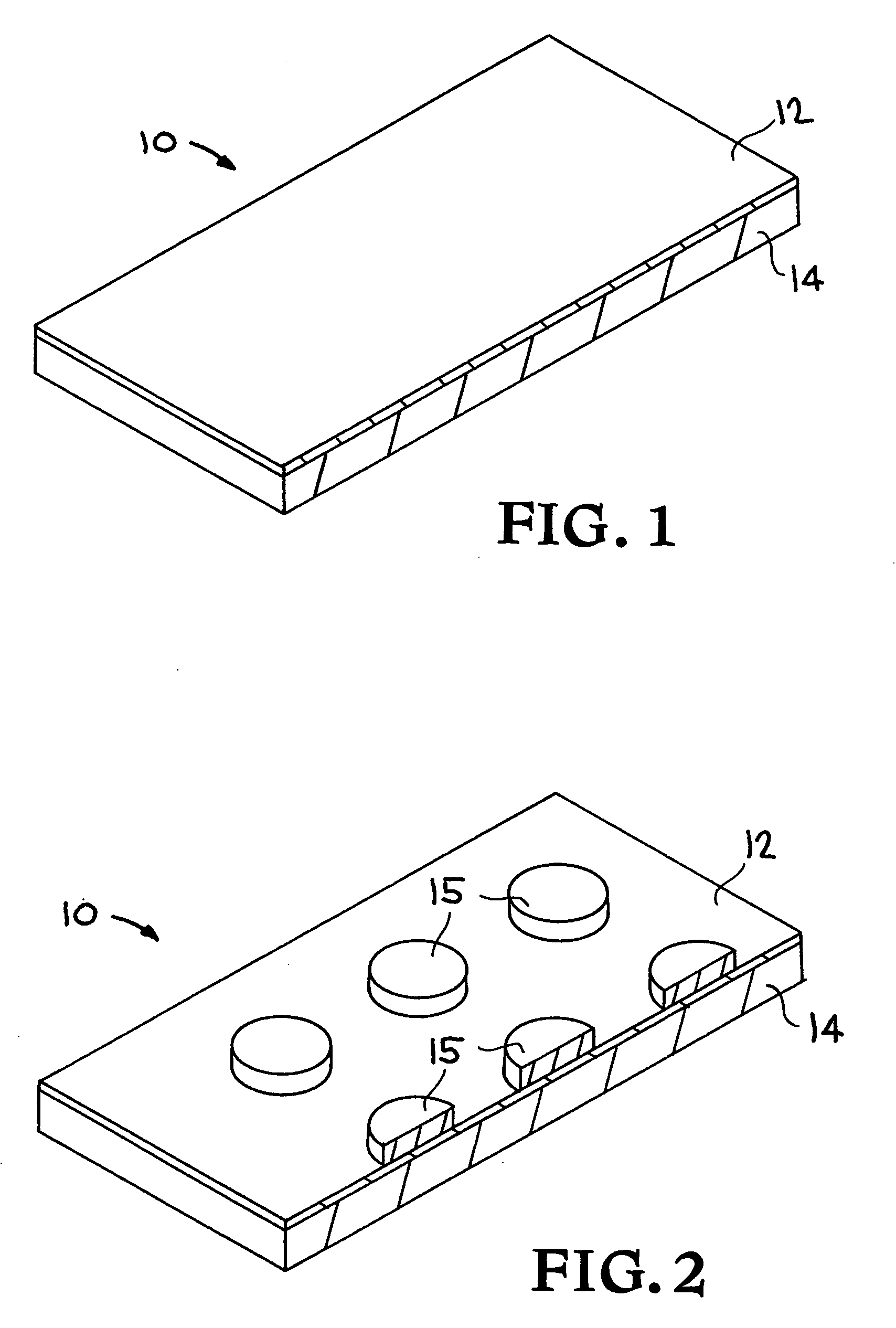
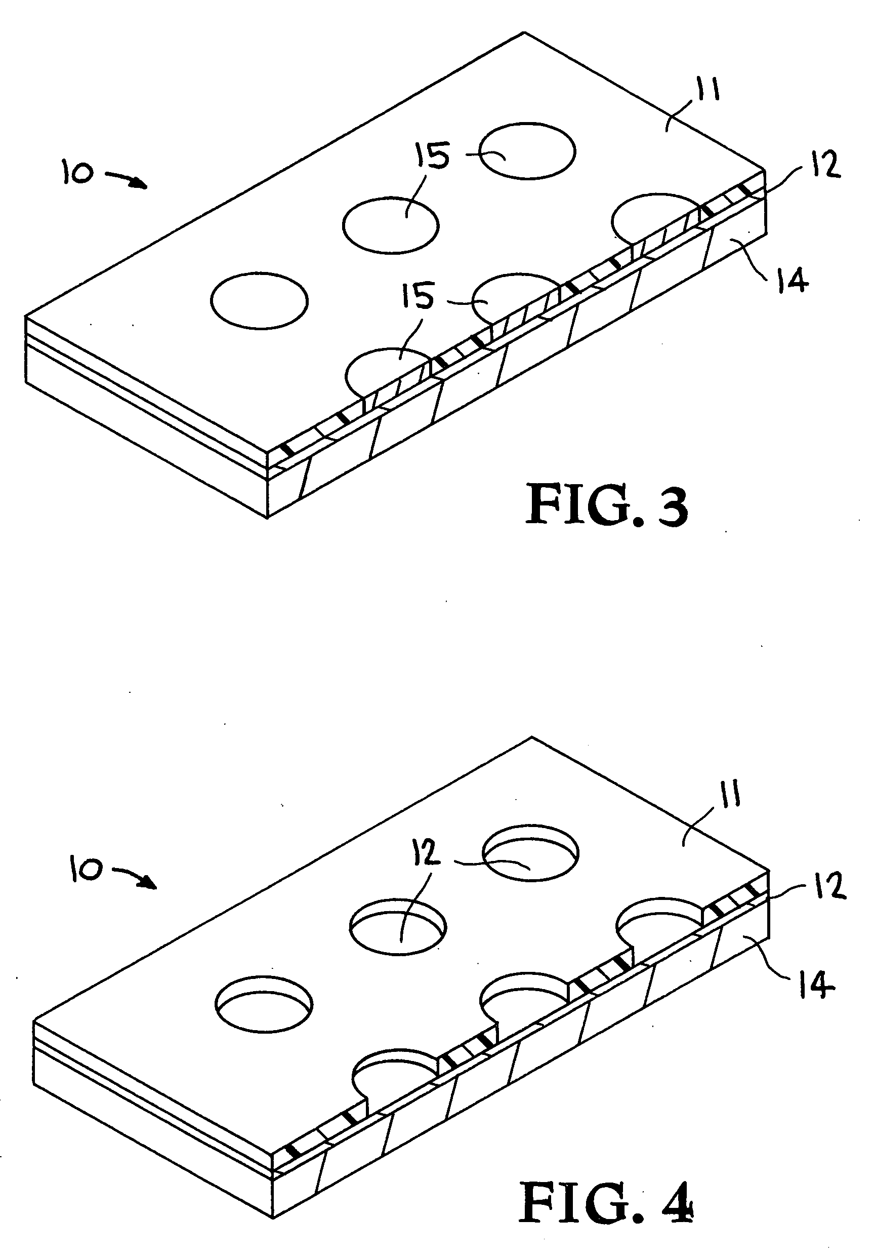
[0030] The present invention provides an electrode array for artificial vision and a system that can be attached to the skin, can be implanted, and has many other uses. In one embodiment an electrode array is provided utilizing a substrate made of a compliant material. Electrodes and conductive leads are embedded in the substrate. The fact that the device can conform to various shapes is advantageous. In one embodiment an electrode array is...


PUM

PropertyMeasurementUnit
RF poweraaaaaaaaaa
temperatureaaaaaaaaaa

Abstract

An image is captured or otherwise converted into a signal in an artificial vision system. The signal is transmitted to the retina utilizing an implant. The implant consists of a polymer substrate made of a compliant material such as poly(dimethylsiloxane) or PDMS. The polymer substrate is conformable to the shape of the retina. Electrodes and conductive leads are embedded in the polymer substrate. The conductive leads and the electrodes transmit the signal representing the image to the cells in the retina. The signal representing the image stimulates cells in the retina.

Description

CROSS-REFERENCE TO RELATED APPLICATIONS [0001] This application is a divisional of U.S. patent application Serial No. 10 / 115,676, filed Apr. 3, 2002, titled “Flexible Electrode Array for Artificial Vision,” which was a continuation of U.S. patent application Ser. No. 09 / 992,248 filed Nov. 16, 2001, titled “Flexible Electrode Array for Artificial Vision.”[0002] The United States Government has rights in this invention pursuant to Contract No. W-7405-ENG-48 between the United States Department of Energy and the University of California for the operation of Lawrence Livermore National Laboratory.BACKGROUND OF THE INVENTION [0003] 1. Field of Endeavor [0004] The present invention relates to electrodes and more particularly to an electrode array that can be used for artificial vision, that can be implanted, that is useful for surgical insertion, that can be attached to the surface of the skin, that can be used as a flex circuit, and that can be used in other ways. [0005] 2. State of Tech...

Claims


Application Information

Patent Timeline
Patent Type & Authority Applications(United States)
IPC IPC(8): A61N1/18A61N1/05
CPCA61N1/0543Y10T29/49165H05K3/205H05K3/4007H05K2201/0162H05K2201/09481H05K2203/0733Y10S623/901Y10S623/90Y10S623/926Y10S623/905Y10T29/49169Y10T29/49224Y10T29/49147Y10T29/49128Y10T29/49155Y10T29/49139Y10T29/4913H05K1/118
Inventor KRULEVITCH, PETERPOLLA, DENNIS L.MAGHRIBI, MARIAM N.HAMILTON, JULIEHUMAYUN, MARK S.WEILAND, JAMES D.
Owner LAWRENCE LIVERMORE NAT SECURITY LLC
Why Eureka
Try Eureka