Twin-clutch device

a technology of twin-clutch and clutch, which is applied in the direction of fluid-actuated clutches, clutches, non-mechanical actuated clutches, etc., can solve the problems of increasing weight, and achieve the effects of reducing inertial mass, reducing weight of the rotary portion, and efficient transmission

Inactive Publication Date: 2007-06-28
HONDA MOTOR CO LTD
View PDF0 Cites 4 Cited by
  • Summary
  • Abstract
  • Description
  • Claims
  • Application Information

AI Technical Summary

Benefits of technology

[0015] According to the first aspect of the invention, since the first and second clutch disconnection / connection control mechanisms are disposed in a non-rotary portion, the weight of the rotary portion is reduced to achieve a reduction in inertial mass, thereby allowing power from the driving rotary member to be efficiently transmitted to the driven rotary member side.
[0016] Further, according to the second aspect of the invention, the twin-clutch device can be made compact with respect to the direction of its rotation axis.
[0017] According to the third aspect of the invention, since the hydraulic pressure chamber equipped in each of the first and second clutch disconnection / connection control mechanisms is provided in a non-rotary portion, no centrifugal force is exerted on the oil in the hydraulic chambers. Accordingly, not only is it unnecessary to provide a mechanism for canceling the hydraulic pressure generated due to a centrifugal force, the weight of the rotary portion can be further reduced because the urging member is also provided in the non-rotary portion, thereby achieving a further reduction in inertial mass.
[0018] According to the fourth aspect of the invention, the oil passage for introducing oil to the hydraulic chamber can be readily formed in the cover, and as compared with the case where the oil passage is formed within a rotary member, it is possible to simplify and shorten the path of the oil passage, thereby achieving reduced hydraulic pressure loss and reduced machining man-hours.
[0019] According to the fifth aspect of the invention, the twin-clutch device can be made compact with respect to its radial direction.
[0020] Further scope of applicability of the present invention will become apparent from the detailed description given hereinafter. However, it should be understood that the detailed description and specific examples, while indicating preferred embodiments of the invention, are given by way of illustration only, since various changes and modifications within the spirit and scope of the invention will become apparent to those skilled in the art from this detailed description.

Problems solved by technology

Accordingly, a mechanism for canceling the hydraulic pressure generated due to the centrifugal force needs to be provided at a position opposed to the hydraulic chamber, which inevitably leads to an increase in weight.

Method used


Image

  • Twin-clutch device
  • Twin-clutch device
  • Twin-clutch device

Examples


Embodiment Construction

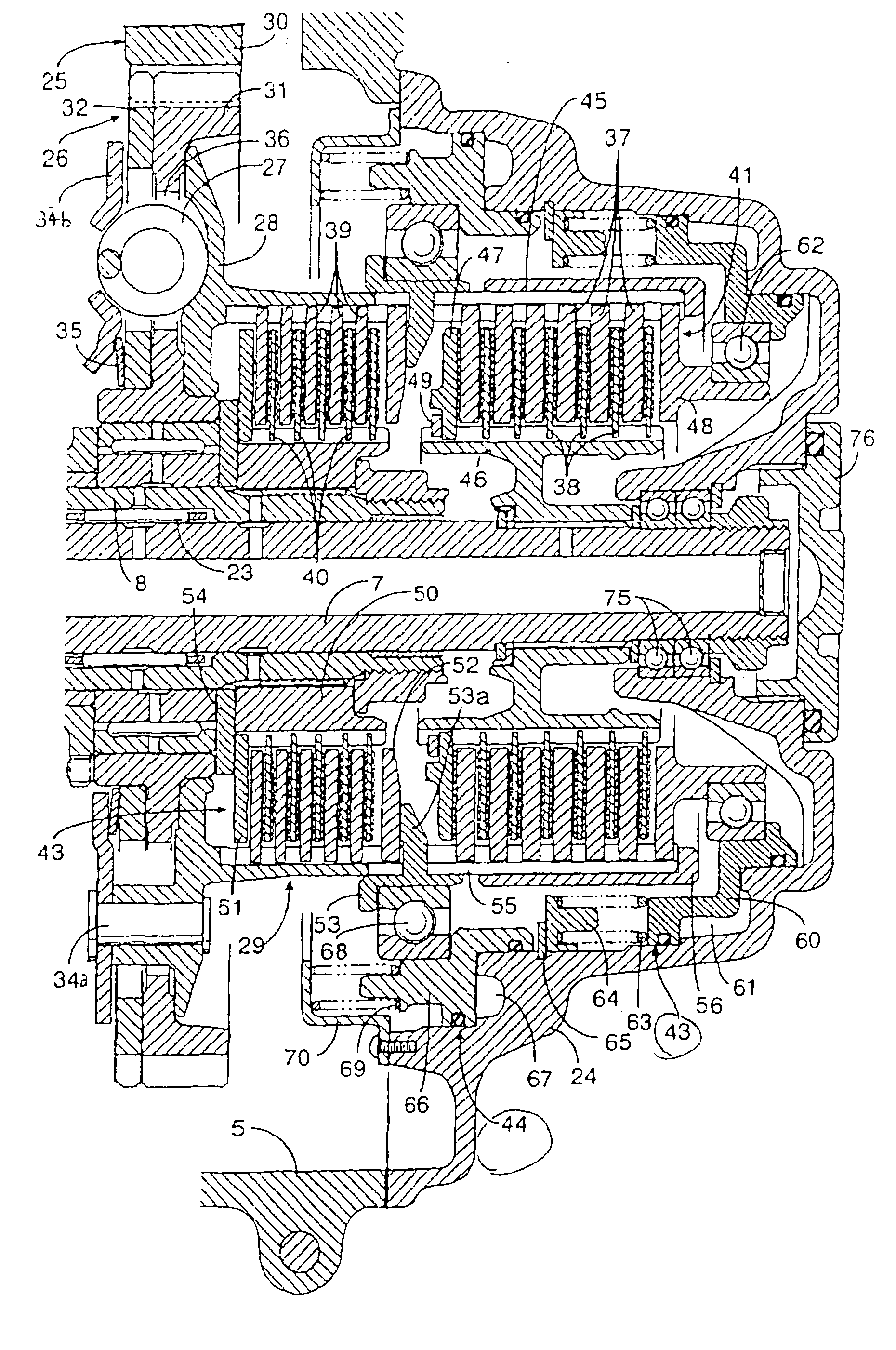
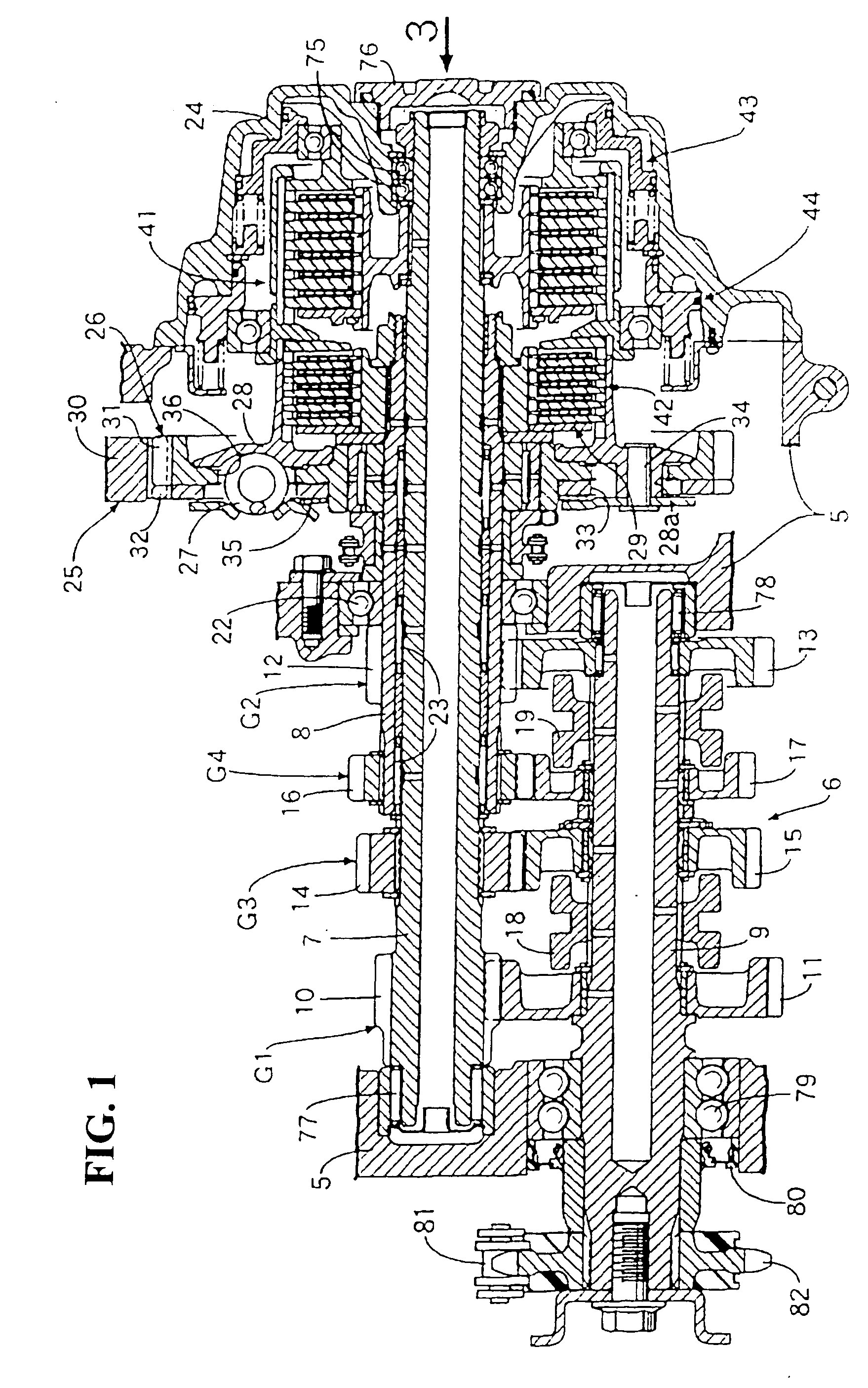
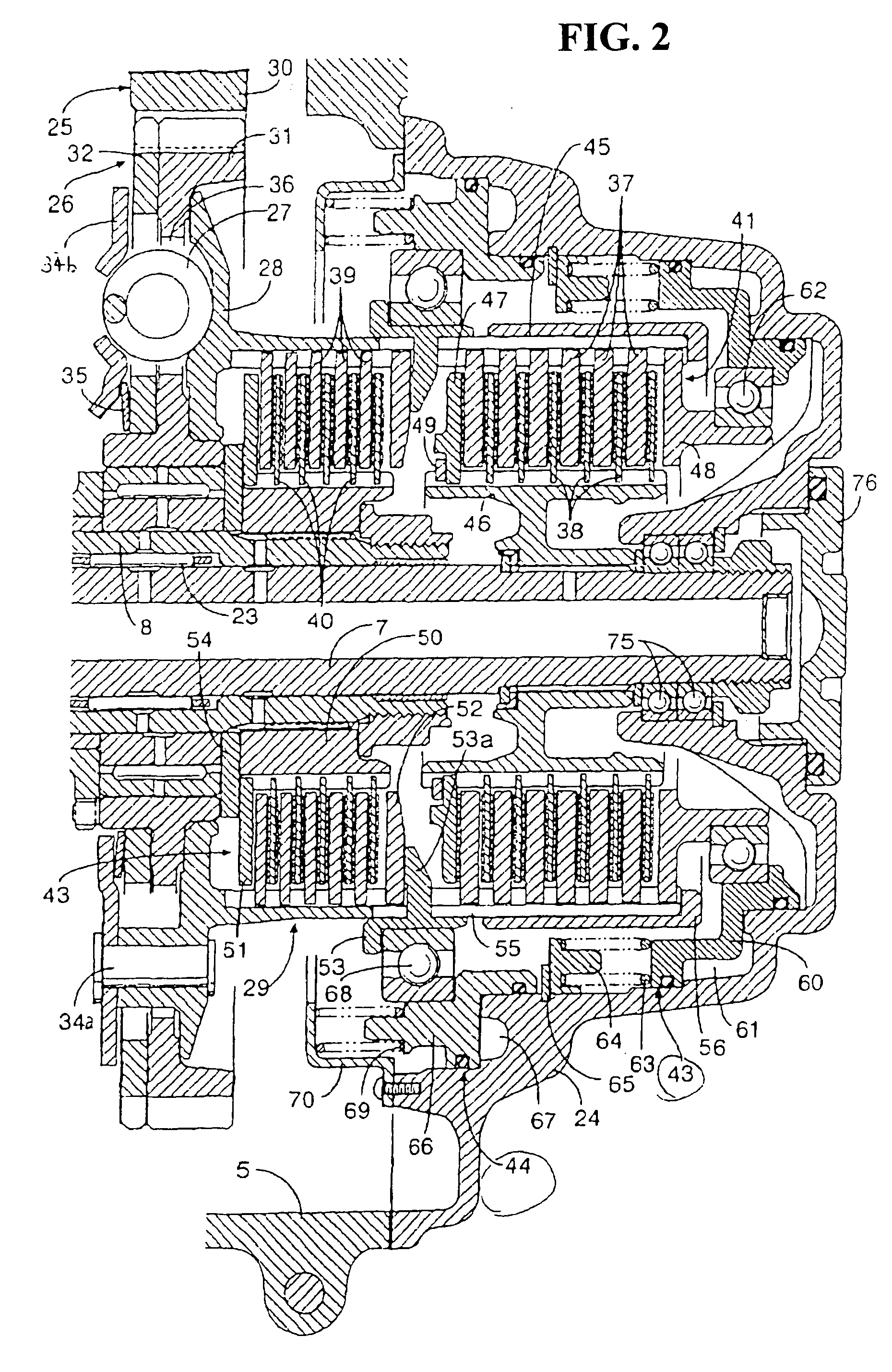
[0025] First, in FIG. 1, for example, a crankcase 5 equipped to an engine mounted to a motorcycle accommodates a transmission 6 including plural speeds of gear trains that can be selectively established, for example, first to fourth-speed gear trains G1, G2, G3, G4. The first-speed gear train G1 includes a first-speed driving gear 10 provided integrally with a first main shaft 7, and a first-speed driven gear 11 rotatably supported on a countershaft 9, which is parallel to the first main shaft 7, and brought into meshing engagement with the first-speed driving gear 10. The second-speed gear train G2 includes a second-speed driving gear 12 provided integrally with a second main shaft 8 that is coaxial with the first main shaft 7, and a second-speed driven gear 13 rotatably supported on the countershaft 9 and brought into meshing engagement with the second-speed driving gear 12. The third-speed gear train G3 includes a third-speed driving gear 14 fixed to the first main shaft 7, and a...


PUM


Abstract

A twin-clutch device includes first and second clutch actuating mechanisms; a first clutch disconnection/connection control mechanism for exerting on the first clutch actuating mechanism a controlling force for switching disconnection/connection of the first clutch actuating mechanism; and a second clutch disconnection/connection control mechanism for exerting on the second clutch actuating mechanism a controlling force for switching disconnection/connection of the second clutch actuating mechanism. The first and second clutch disconnection/connection control mechanisms include control actuating members that are supported on a fixing member in a non-rotating state while being allowed to move in a direction along rotation axes of a first driven rotary member and second driven rotary member, the control actuating members being respectively connected to first and second clutch actuating mechanisms via bearings. The clutch so configured reduces the inertial mass by reducing the weight of the rotary portion of the clutch.

Description

CROSS-REFERENCE TO RELATED APPLICATION [0001] The present application claims priority under 35 U.S.C. §119 to Japanese Patent Application No. 2005-377450, filed Dec. 28, 2005, the entire contents of which are hereby incorporated by reference. BACKGROUND OF THE INVENTION [0002] 1. Field of the Invention [0003] The present invention relates to a twin-clutch device including a first clutch actuating mechanism having a plurality of first and second friction plates arranged in an alternately overlapping manner, for switching disconnection / connection of power transmission between a driving rotary member and a first driven rotary member and a second clutch actuating mechanism having a plurality of third and fourth friction plates arranged in an alternately overlapping manner, for switching disconnection / connection of power transmission between the driving rotary member and a second driven rotary member. The device also includes a first clutch disconnection / connection control mechanism for ...

Claims


Application Information

Patent Timeline
Patent Type & Authority Applications(United States)
IPC IPC(8): F16D21/02
CPCF16D25/10F16D25/082F16D2021/0661F16D21/06
Inventor IEDA, YOSHIHISATOMODA, AKIHIKOKANNO, YOSHIHISA
Owner HONDA MOTOR CO LTD
Why Eureka
Try Eureka