Pedaling correction device for bicycle

Inactive Publication Date: 2007-06-28
MATSUMOTO HITOSHI
View PDF9 Cites 10 Cited by
  • Summary
  • Abstract
  • Description
  • Claims
  • Application Information

AI Technical Summary

Benefits of technology

[0019] Thus, the invention provides the effective assist in the pedaling training utilizing the modified crank gear which is adapted to indicate the point for the cyclist to start exerting the pressure upon the pedal by allowing the cyclist to experience a varied torque, so as to urge the cyclist to exert the maximum pressure upon the pedal at the crank angular point at which the cyclist desires to and/or should exert the maximum pressure upon the pedal in one pedal stroke. The use of the invention offers an additional effect that the

Problems solved by technology

The “required great force” means that a great torque or pedaling force is required.
Only the effective pedaling force contributes to the driving of the bicycle whereas the ineffective pedaling force is totally useless, simply wasting the cyclist's stamina.
In actual fact, however, the following problems are encountered.
Therefore, it is difficult for each cyclist undergoing the training to determine whether or not the cyclist has accomplished the pedaling motion exactly following the theory.
This is disadvantageous to the cyclist whereas the trainer is not convincing enough to train the cyclist.
That is, although the cyclist understands the theory, it is difficult for the cyclist to unconsciously and continuously perform the following motion for long hours

Method used


Image

  • Pedaling correction device for bicycle
  • Pedaling correction device for bicycle
  • Pedaling correction device for bicycle

Examples


Example

EXAMPLE 1

[0035] A flow of actual preparation of the modified crank gear dedicated to each cyclist and an embodiment wherein a bicycle equipped with the modified crank gear thus prepared is used for the pedaling training will be described as below. FIG. 3 is a fragmentary view of a crank gear portion of a pedaling training assist device 1 according to one embodiment of the invention. A crank gear G shown in the figure is an example of the modified crank gear (standard type) fabricated based on necessary requirements decided according to a procedure described as below.

[0036] When a long axis of the modified crank gear G is in the vicinity of the top dead center as shown in FIG. 3, a chain engages the crank gear as stretched aslant relative to the horizontal direction. Therefore, a start point of engagement with the chain is slightly shifted backward from the top dead center with respect to the rotational direction of the crank gear.

[0037] When the long axis of the crank gear G and ...

Example

EXAMPLE 2

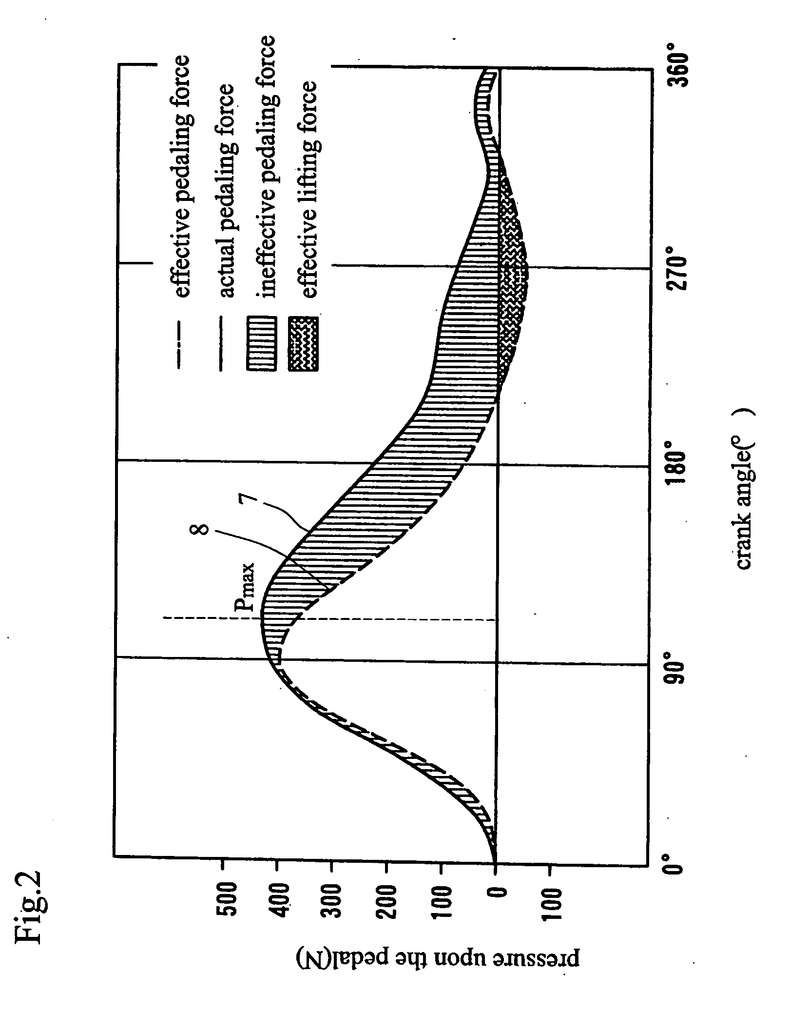
[0050]FIG. 5 illustrates another example of the pedaling training assist device of the invention. This device includes a cycling machine M equipped with the modified crank gear G fabricated according to the above procedure. The machine also has a crank angle sensor S and a pedal pressure sensor Q mounted thereto. Output signals from these sensors are subjected to computation by a control unit 10 incorporated in the cycling machine M. Thus, a point Pmax (see FIG. 2) where the pressure actually exerted upon the pedal by the cyclist is at maximum is shown on a display 11 in the form of “so-and-so crank angular position”, whereby the cyclist is informed of the cyclist's pedaling conditions. The display 11 is adapted to sequentially show an average value of Pmax (crank angular position) or the like once in several crank strokes or at regular time intervals. The cycling machine M may be, for example, one installed at a fitness gym. This example employs the cycling machine adapte...

Example

EXAMPLE 3

[0052] The example illustrates a telemetry system for determining the pedaling conditions. The system is principally used at a site of a track-like go-around course as a training field, where the cyclist actually rides the bicycle on the course while the system is operated for the purposes of (1) acquiring pedaling data, and (2) determining the pedaling inclinations, the results of the training and the like.

[0053] In the pedaling correction system 1 shown in FIG. 6, the crank angle sensor S is mounted in a body of the bicycle B whereas the pedal pressure sensor Q is mounted to the pedal. The output signals from these sensors are supplied to a control unit 24, where processing is performed for determining the point Pmax where the pressure actually exerted upon the pedal by the cyclist is at maximum. Subsequently, data indicative of the average value of the Pmax (crank angular position) calculated from average data determined once in several crank strokes, for example, are ...


PUM


Abstract

A pedaling correction device for a bicycle capable of objectively detecting the state of pedaling and assisting the detection so that the training of pedaling technique can be performed according to an accurate theory. The cranks having pedals mounted at the tips thereof are installed on the center axis of the device so that a crank gear can be rotated according to the rotation of the cranks. The state of the pedaling of a user is monitored and the shape of the crank gear is deformed so that when the cranks reach positions where the user must increase forces applied to the pedals, the vertical diameter of the crank gear can be increased. Also, when the cranks reach positions where the user must release forces applied to the pedals, the vertical diameter of the crank gear can be reduced, whereby the correction of pedaling can be assisted by using such a crank gear.

Description

TECHNICAL FIELD [0001] The present invention relates to an assist device used for training for a so-called pedaling technique to pedal a bicycle efficiently and speedily. BACKGROUND ART [0002] First, an outline of the general power transmission mechanism in bicycle is given. [0003]FIG. 1 shows a drive system of a bicycle. In the figure, arrows F1 to F3 represent a transmission direction of a drive force, respectively, whereas r1 to r4 represent a length of a crank C, a distance between a top dead center and a central axis of a crank gear 5, a radius of a hub gear 6 and a radius of a rear wheel 4, respectively. [0004] As shown in FIG. 1, the bicycle is driven by converting a reciprocating motion of the legs into a rotating motion. In this process, the leg motion is magnified based on a ratio between the radii of the crank gear 5 and the hub gear 6 mounted on a central axis of the rear wheel 4, or based on a leverage, and is finally transmitted to the rear wheel. The leverage is decid...

Claims


Application Information

Patent Timeline
IPC IPC(8): B62M1/02B62M1/36A63B69/16B62H7/00B62M3/06
CPCA63B69/16A63B2220/16A63B2220/56B62H7/00B62M1/36B62M3/06B62M2003/006A63B2022/0623B62M9/08B62M2009/002
Inventor MATSUMOTO, HITOSHI
Owner MATSUMOTO HITOSHI
Why Eureka
Try Eureka