Light source device, optical scanning device, and image forming apparatus

a light source device and scanning technology, applied in the field of light source devices, optical scanning devices, and image forming apparatuses, can solve the problems of image density, difficult for an image forming apparatus using the light source device to produce a high-quality image, and difficult to increase the rotational speed of a polygon mirror above a certain level, so as to achieve accurate detection of the intensity of a light beam emitted and high-quality image

Inactive Publication Date: 2007-06-28
RICOH KK
View PDF7 Cites 47 Cited by
  • Summary
  • Abstract
  • Description
  • Claims
  • Application Information

AI Technical Summary

Benefits of technology

[0054] Another embodiment of the present invention provides a small and low-cost optical scanning device including a light intensity detecting unit that can accurately detect the inte...

Problems solved by technology

However, a higher rotational speed increases noise and heat generated by an optical scanning device and therefore it is difficult to increase the rotational speed of a polygon mirror above a certain level.
However, to use a surface emitting laser instead of an edge emitting laser as a light source for a conventional optical scanning device, some problems as described below must be solved.
The fluctuation in the light output level causes unevenness in image density and thereby makes it difficult for an image forming apparatus using the light source device to produce a high-quality image.
However, technologies disclosed in the above patent documents have disadvantages as described below.
However, since the divergence angle of a light beam emitted from a surface emitting laser changes as the driving current changes, the amount of the light beam that can pass through an aperture, which is a beam-limiting unit provided between a surface emitting laser and a beam deflector, may change.
However, increasing the size of a photodetector may reduce the responsivity of the photodetector.
Although it is possible to reduce the size of a photodetector by adding a light focu...

Method used


Image

  • Light source device, optical scanning device, and image forming apparatus
  • Light source device, optical scanning device, and image forming apparatus
  • Light source device, optical scanning device, and image forming apparatus

Examples


first embodiment

[0123] An exemplary optical scanning device according to a first embodiment is described below.

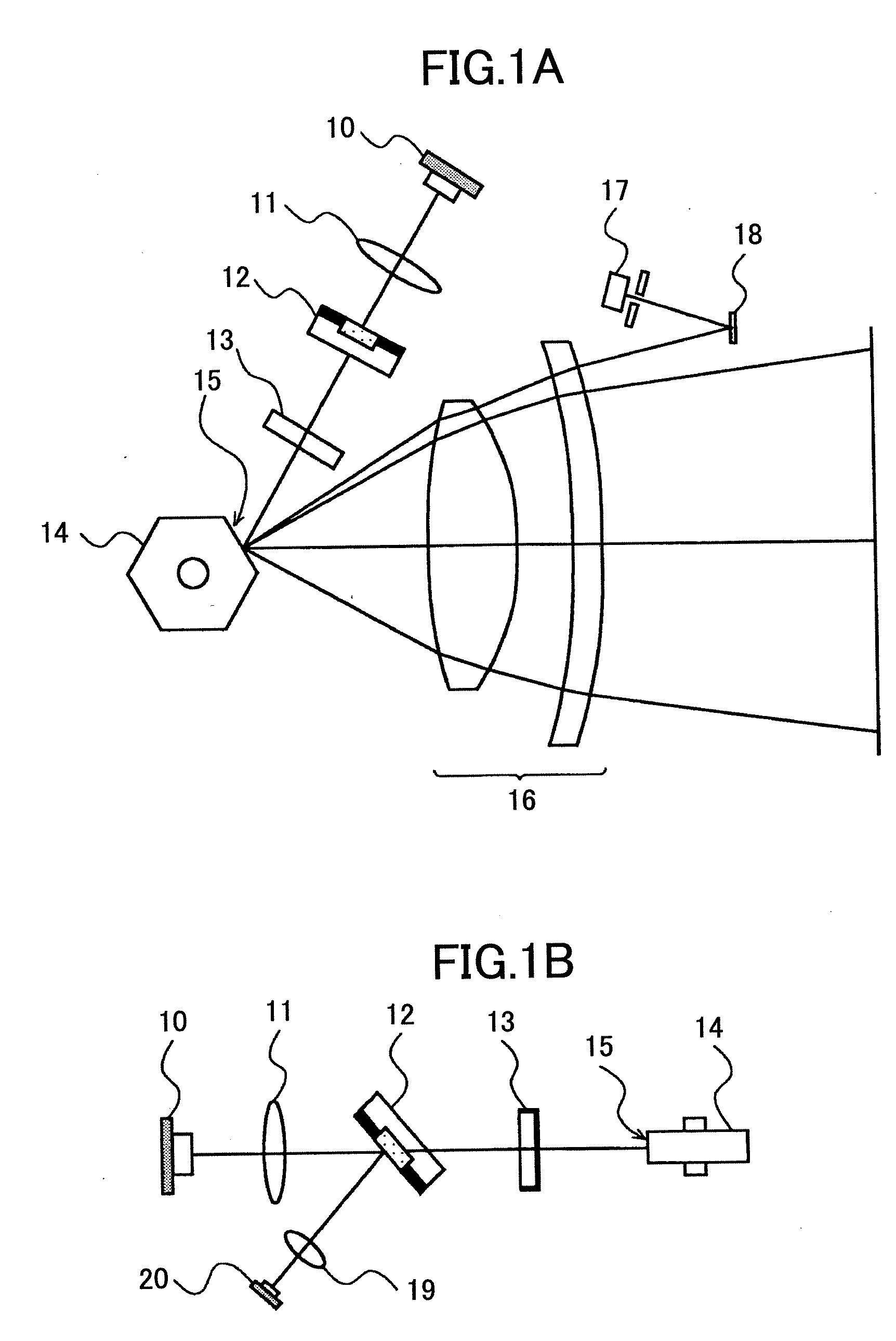
[0124]FIGS. 1A and 1B are drawings illustrating an exemplary configuration of the exemplary optical scanning device according to the first embodiment of the present invention.

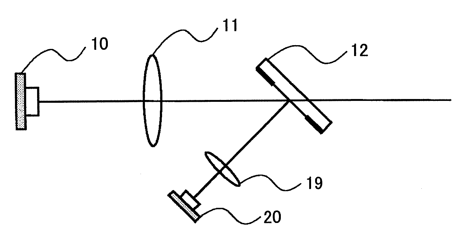
[0125] As shown in FIGS. 1A and 1B, the exemplary optical scanning device according to the first embodiment includes a VCSEL 10, a coupling lens 11, a beam limiting / splitting unit 12, a cylindrical lens 13, a polygon scanner 14 having deflecting reflective surfaces 15, fθ lenses 16, a synchronizing sensor 17, a reflection mirror 18, an optical unit 19, and a photodetector 20.

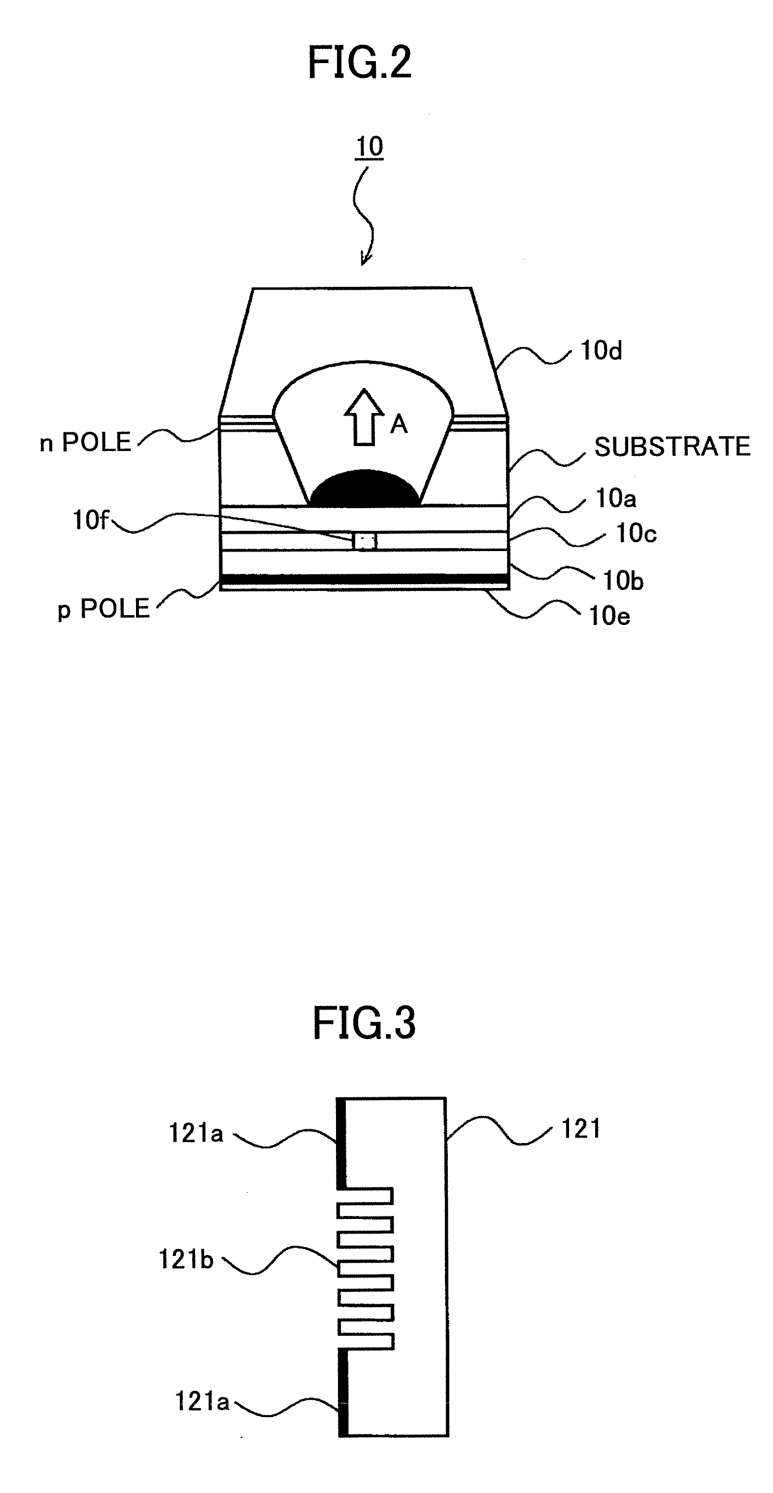
[0126] The VCSEL (vertical cavity surface emitting laser) 10 is a light source. Either a single-VCSEL having one light-emitting point or a multi-beam VCSEL having multiple light-emitting points may be used as the VCSEL 10. A divergent light beam emitted from the VCSEL 10 enters a coupling unit for converting the divergent light beam into a ligh...

second embodiment

[0191] An exemplary optical scanning device according to a second embodiment is described below. In the exemplary optical scanning device, a beam-limiting unit and a beam-splitting unit are provided separately.

[0192]FIG. 17 is a drawing illustrating an exemplary configuration of the exemplary optical scanning device according to the second embodiment of the present invention.

[0193] In the exemplary optical scanning device of the second embodiment, the beam limiting / splitting unit 12 in the exemplary optical scanning device of the first embodiment is divided into a beam-limiting unit 12A and a beam-splitting unit 21.

[0194] As shown in FIG. 17, the exemplary optical scanning device according to the second embodiment includes a VCSEL 10, a coupling lens 11, the beam-limiting unit 12A, a cylindrical lens 13, a polygon scanner 14 having deflecting reflective surfaces 15, fθ lenses 16, a synchronizing sensor 17, a reflection mirror 18, an optical unit 19, a photodetector 20, and the be...


PUM


Abstract

A disclosed device for optically scanning a target surface includes a light source unit configured to emit a light beam; a light intensity detecting unit; a coupling unit configured to substantially collimate the emitted light beam; a beam limiting unit configured to limit the amount of the collimated light beam; a beam splitting unit configured to split the beam limited light beam and thereby to cause a first portion of the beam limited light beam to enter the light intensity detecting unit, wherein the light intensity detecting unit is configured to detect the intensity of the first portion of the beam limited light beam; and a beam deflecting unit configured to deflect a second portion of the split light beam toward the target surface. In the disclosed device, the beam limiting unit and the beam splitting unit are integrated as a single unitary structure and positioned between the coupling unit and the light deflecting unit.

Description

BACKGROUND OF THE INVENTION [0001] 1. Field of the Invention [0002] The present invention generally relates to a light source device, an optical scanning device, and an image forming apparatus, and more particularly relates to a light source device including a surface emitting laser or a surface emitting laser array and having light intensity control and polarization control mechanisms; an optical scanning device including a beam-splitting unit for splitting a laser beam and thereby enabling the detection of the intensity of the light beam; and an image forming apparatus including the light source device and / or the optical scanning device. [0003] 2. Description of the Related Art [0004] In an image forming apparatus such as a laser printer or a digital copier, a latent image (electrostatic latent image) is formed on a photoconductor by focusing a light beam, which is emitted from a light source and modulated according to image data, via a beam deflector and a scanning lens onto the ...

Claims


Application Information

Patent Timeline
IPC IPC(8): B41J2/435
CPCB41J2/471G02B26/124G02B27/108G02B27/1093G02B27/144G02B27/283
Inventor MASUDA, KOJI
Owner RICOH KK
Why Eureka
Try Eureka