Liquid crystal display having a modified electrode array

a liquid crystal display and electrode array technology, applied in non-linear optics, instruments, optics, etc., can solve the problems of black state, white state, tn-lcd narrow viewing angle, etc., and achieve the effect of wide viewing angl

Inactive Publication Date: 2007-06-28
SAMSUNG DISPLAY CO LTD
View PDF20 Cites 11 Cited by
  • Summary
  • Abstract
  • Description
  • Claims
  • Application Information

AI Technical Summary

Benefits of technology

[0014] An object of the present invention is to obtain a wide viewing angle.

Problems solved by technology

Consequently, the light cannot pass through the analyzer, thereby causing black state.
However, when sufficient electric field is applied to the liquid crystal layer, the polarization of the incident light varies and the light passes through the analyzer, thereby causing a white state.
The principal disadvantage of the TN-LCD is its narrow viewing angle.
Accordingly, the viewing angle that provides the contrast of 10 is very narrow, and thus image quality is deteriorated when viewed at an angle greater than the viewing angle.
To compensate the viewing angle, methods using phase difference compensating films are suggested in U.S. Pat. No. 5,576,861, but they have disadvantages in manufacturing cost and the number of the process steps since the phase difference compensating films are additionally attached.
Furthermore, the satisfactory viewing angle may not be still obtained even though the phase retardation compensation films are used.
The U.S. Pat. No. 5,598,285 also has disadvantages in power consumption and aperture ratio.
However, the former method may increase the manufacturing cost and the number of process steps, and the latter may cause uneven rubbing.

Method used


Image

  • Liquid crystal display having a modified electrode array
  • Liquid crystal display having a modified electrode array
  • Liquid crystal display having a modified electrode array

Examples


first embodiment

[0090] First, an LCD according to the present invention is described in detail with reference to FIGS. 1 through 11.

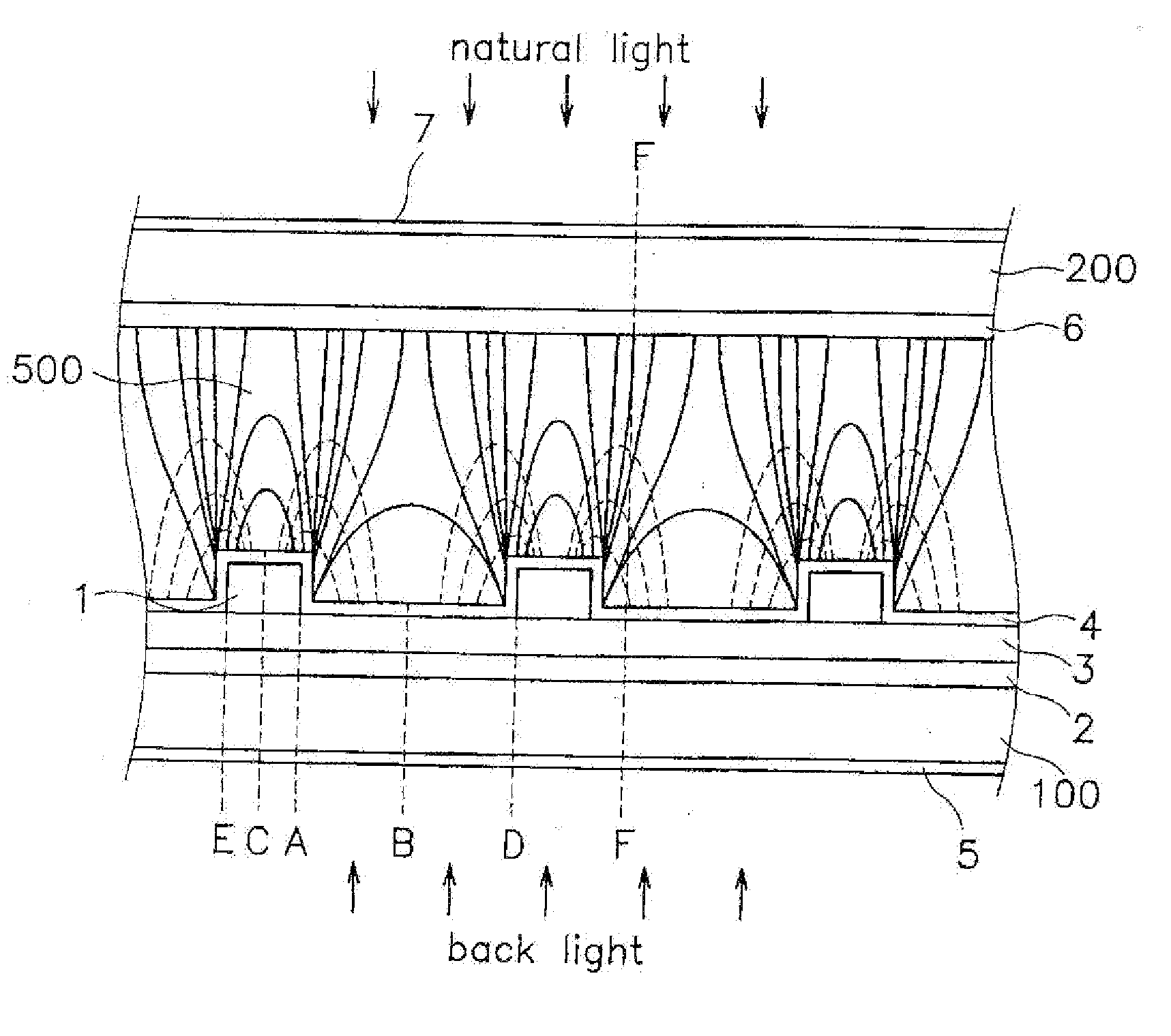
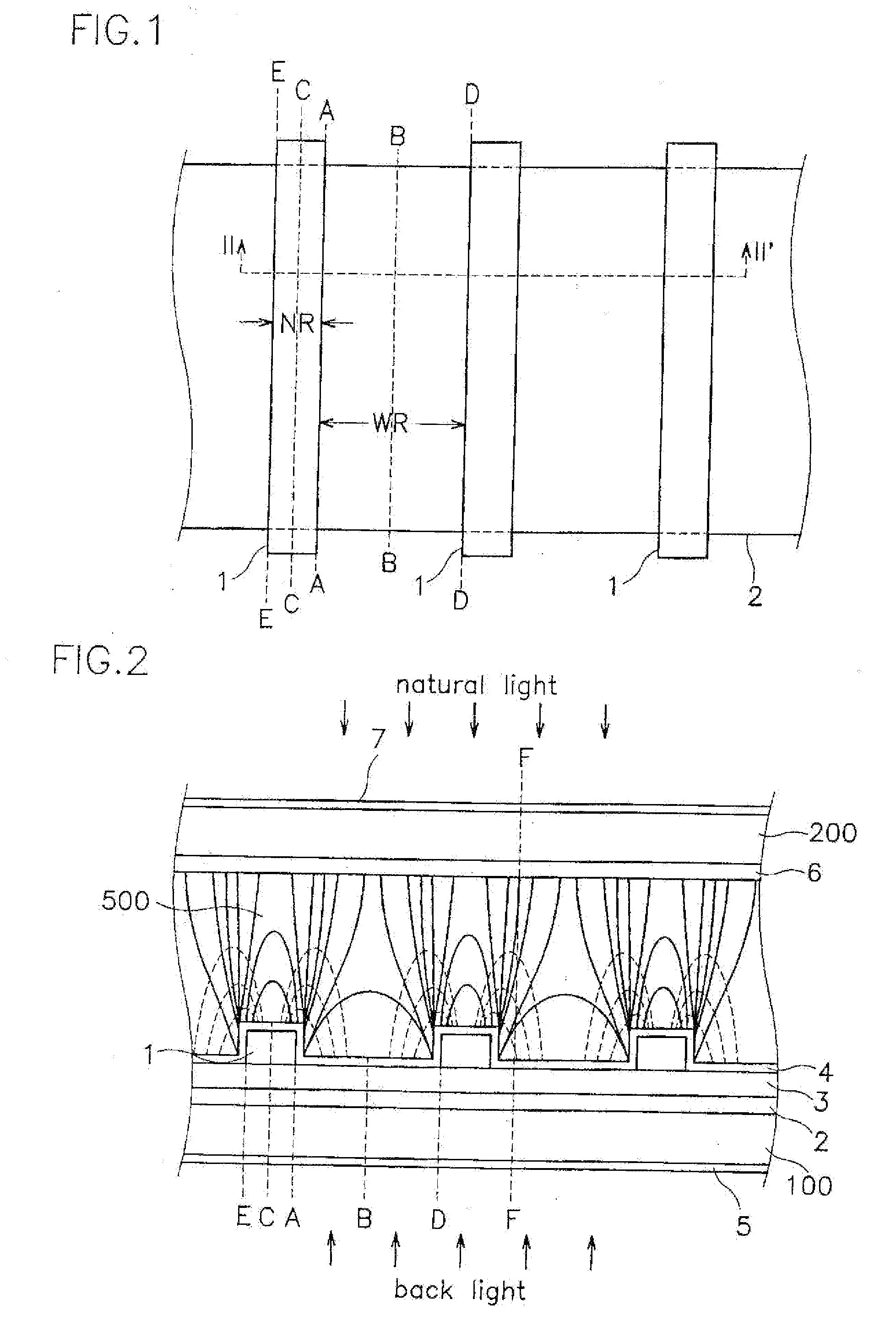
[0091]FIG. 1 is a layout view of electrodes of an LCD according to the first embodiment of the present invention, and FIG. 2 is a cross-sectional view taken along the line II-II′ in FIG. 1, which illustrates both upper and lower substrates as well as equipotential lines and lines of electrical force between the substrates.

[0092] First, the structures of a lower substrate on which electrodes are formed and an upper substrate of the LCD are described in detail.

[0093] A planar electrode 2 made of transparent conductive material such as indium tin oxide (ITO) is formed on the inner surface of a lower substrate 100 made of a transparent insulating material such as glass or quartz. The planar electrode 2 has a predetermined longitudinal width and is elongated in the transverse direction. The planar electrode 2 is covered with an insulating film 3, and a plurality of narrow...

second embodiment

[0135] The second embodiment uses a liquid crystal having negative dielectric anisotropy.

[0136] The structure of an LCD according to the second embodiment is similar to the first embodiment, and thus the shape of the electric field is similar. However, the rearrangement of the liquid crystal molecules due to the electric field is different than that of the first embodiment.

[0137] In the initial state, the two aligning films 4 and 6 are rubbed or exposed to ultraviolet light, and the liquid crystal molecules are aligned in one horizontal direction. The liquid crystal molecules may have some pre-tilt angle of less than 7 degrees with respect to the substrates 100 and 200 but they are aligned substantially parallel to the substrates 100 and 200. When viewed on a plane parallel to the substrates 100 and 200, the liquid crystal molecules are arranged to have a predetermined angle of equal to or less than 45 degrees with respect to the directions parallel and perpendicular to the linear ...

third embodiment

[0157] The third embodiment uses a liquid crystal having positive dielectric anisotropy but the liquid crystal molecules in their initial states are perpendicular to the substrates.

[0158] The structure of an LCD according to the third embodiment is similar to the first embodiment, and thus the shape of the electric field is similar. However, the rearrangement of the liquid crystal molecules due to the different initial states is different than that of the first embodiment.

[0159] In the initial state, the two aligning films 4 and 6 are rubbed or exposed to ultraviolet light, and the liquid crystal molecules are aligned perpendicular to the substrates 100 and 200. The liquid crystal molecules may have some pre-tilt angle with respect to the substrates 100 and 200 but they are aligned substantially perpendicular to the substrates 100 and 200. When viewed on a plane parallel to the substrates 100 and 200, the liquid crystal molecules are arranged to have a predetermined angle with resp...


PUM

PropertyMeasurementUnit
transmittanceaaaaaaaaaa
angleaaaaaaaaaa
angleaaaaaaaaaa

Abstract

A liquid crystal display having electrodes on a single substrate. A transparent planar electrode elongated in the transverse direction is formed on the inner surface of a substrate, and an insulating film is deposited thereon. A plurality of linear electrodes, which are elongated in the longitudinal direction and either transparent or opaque, are formed on the insulating film. Potential difference between the planar and the linear electrodes generated by applying voltages to the electrodes yields an electric field. The electric field is symmetrical with respect to the longitudinal central line of the linear electrodes, and has parabolic or semi-elliptical lines of force having a center on a boundary line between the planar and the linear electrodes. The line of force on the planar and the linear electrodes and on the boundary line between the planar and the linear electrodes has the vertical and the horizontal components, and the liquid crystal molecules are re-arranged to have a twist angle and a tilt angle. The polarization of the incident light varies due to the rearrangement of the liquid crystal molecules.

Description

CROSS-REFERENCE TO RELATED APPLICATIONS [0001] This application is a Continuation of U.S patent application Ser. No. 10 / 389,888, filed on Mar. 18, 2003, which is a divisional of U.S. patent application Ser. No. 09 / 184,953, filed on Nov. 3, 1998, now U.S. Pat. No. 6,577,368, and which claims priority to Korean Patent Application No. 1997-57823, filed Nov. 3, 1997, Korean Patent Application No. 1998-1702, flied on Jan. 21, 1998, Korean Patent Application No, 1998-5288, filed on Feb. 20, 1998 Korean Patent Application No. 1998-6087, filed on Feb. 26, 1998, Korean Patent Application No. 1998-8231, filed on Mar. 12, 1998, Korean Patent Application No. 1998-8233, filed on Mar. 12, 1998, and Korean Patent Application No. 1998-8235, filed on Mar. 12, 1998, all of which are fully incorporated herein by reference.FIELD OF THE INVENTION [0002] The present invention relates to a liquid crystal display (LCD). More particularly, the present invention relates to an LCD having a modified electrode ...

Claims


Application Information

Patent Timeline
Patent Type & Authority Applications(United States)
IPC IPC(8): G02F1/1343G02F1/136G02F1/1368
CPCG02F1/134363G02F2001/134372G02F2001/134381G02F1/134372G02F1/134381
Inventor YUH, JIN-TAELEE, KYE-HUNNA, BYOUNG-SUNKIM, DONG-GYUCHANG, JONG-WOONGSHIM, JUNG-UKSONG, JANG-KUNLEE, HYUN-SIK
Owner SAMSUNG DISPLAY CO LTD
Why Eureka
Try Eureka