Method and systems for forming and using nanoengineered sculptured thin films

a technology of nano-engineered sculptures and thin films, applied in the field of nano-engineered sculptured thin films, can solve the problems of degrading biopolymers, affecting the differentiation of cells, and affecting the adhesion of cells, so as to promote cell differentiation, proliferation, and adhesion

Inactive Publication Date: 2007-06-28
PENN STATE RES FOUND
View PDF30 Cites 10 Cited by
  • Summary
  • Abstract
  • Description
  • Claims
  • Application Information

AI Technical Summary

Benefits of technology

[0007] It is a further object, feature, or advantage of the present invention to provide for a method for forming sculptured thin films.
[0008] It is a further object, feature, or advantage of the present invention to provide for the use of biocompatible and bioactive STFs that can made of organic and inorganic materials such as, without limitation, polymers, oxides, and metals.
[0009] Another object, feature, or advantage of the present invention to provide biocompatible and bioactive STFs which can be used with human cells, including HEK-293 human kidney cells and COS7 fibroblast cells.
[0010] Yet another object, feature, or advantage of the present invention is to provide means to promote cell differentiation, proliferation, and adhesion that can be designed to suit different types of cellular matter.
[0011] A further object, feature, or advantage of the present invention is to provide a biocompatible material that can be made through a direct one-step growth procedure without requiring masking and / or lithography.
[0012] A still further object, feature, or advantage of the present invention is to provide a biocompatible material which can be deposited on topographic substrates.

Problems solved by technology

However, the long-term degradation of silicon interacting with biofluids is problematic, and the structures made heretofore require complicated and expensive techniques (e.g., lithography and masking).
However, elevated medically significant environmental factors (e.g., temperature, pH, contaminants, and sterilizing agents and detergents) degrade biopolymers.
Therefore, despite various advances made problems remain.

Method used


Image

  • Method and systems for forming and using nanoengineered sculptured thin films
  • Method and systems for forming and using nanoengineered sculptured thin films
  • Method and systems for forming and using nanoengineered sculptured thin films

Examples


Embodiment Construction

I. Formation of Polymeric STFs

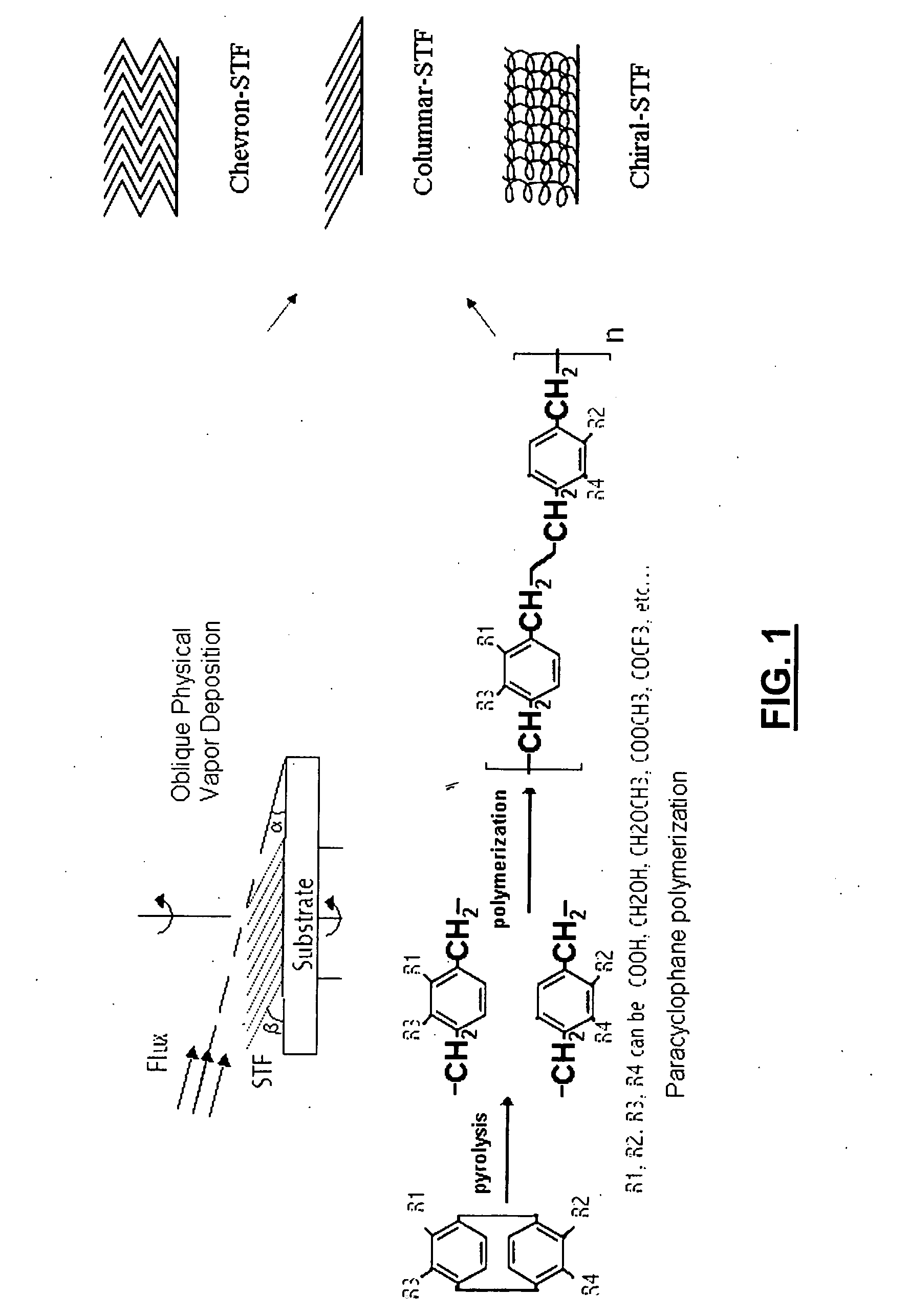
[0041] The present invention provides for the formation of polymeric sculptured thin films (STFs) through use of a combination of physical and chemical vapor deposition processes. The process allows the shapes of submicron and nanowire assemblies to be engineered so that the resulting polymeric STF acts as a template for preferential attachment of biomolecules.

[0042]FIG. 1 is a pictorial representation of a method of forming polymeric STFs. The process of growing the STFs may be grown in a commercial reactor such as the Parylene Deposition System (PDS) 2010 from Cookson Electronics modified through the addition of a nozzle for controlling direction of vapor deposition and through addition of a motorized assembly to control movement of the substrate. The deposition process involves vaporization of the dimer until it sublimes pyrolysis to form the monomer and polymerization of the parylene or other polymer on the substrate. Note that chemical and physica...


PUM

PropertyMeasurementUnit
diameteraaaaaaaaaa
diameteraaaaaaaaaa
diameteraaaaaaaaaa

Abstract

A method of forming a sculptured thin film on a surface includes rotating the surface and depositing a sculptured thin film comprised of a polymer on the surface to form submicron wires during the step of rotating. The submicron wires may be columnar, helically columnar, chevron shaped, chiral shaped, distinct or interwoven. The depositing step may involve pyrolizing the polymer into a vapor of monomers, directing the vapor of monomers towards the surface while rotating the surface, and polymerizing the monomers on the surface. The surface may be incorporated into biomedical device or other biological application where the sculptured thin film is biocompatible and bioactive and adapted for a biological use.

Description

CROSS-REFERENCE TO RELATED APPLICATIONS [0001] This application claims priority under 35 U.S.C. § 119 to U.S. Provisional Patent Application No. 60 / 753,025, filed Dec. 22, 2005, herein incorporated by reference in its entirety.BACKGROUND OF THE INVENTION [0002] The present invention relates to nanoengineered sculptured thin films, and more particularly to nanoengineered sculptured thin films suitable for biological uses. Various references in the prior art have discussed the formation of sculptured thin films. Among these are U.S. Pat. No. 5,866,204 to Robbie et al. and U.S. Pat. No. 6,248,422 also to Robbie et al., which refer to sculptured thin film as sculpted thin film [1,2] and a corresponding publication [3]. To be clear, sculpted thin film refers to deposited films deposited in a manner to simulate a geometric form. Earlier works illustrate that as early as 1959 it was known to provide a substrate which is (i) inclined at a fixed angle about an axis parallel to the substrate ...

Claims


Application Information

Patent Timeline
Patent Type & Authority Applications(United States)
IPC IPC(8): A61F2/00B05D3/00
CPCA61L27/34A61L27/54A61L29/085A61L29/16A61L31/10A61L31/16A61L2300/00A61L2420/02B05D1/002B05D1/60C08L65/04
Inventor DEMIREL, MELIK C.LAKHTAKIA, AKHLESH
Owner PENN STATE RES FOUND
Why Eureka
Try Eureka