Electromagnetically driven valve

a technology of electromagnetic actuator and valve body, which is applied in the direction of valve operating means/release devices, machines/engines, etc., can solve the problems of large sound produced by collision between the oscillating arm and the electromagnet, insufficient quiet when the electromagnetic actuator is driven, and the arm tends to be fractured in the vicinity of the first end, so as to improve the durability of the electromagnetically driven valve, the root portion can be strengthened, and the thickness is large.

Inactive Publication Date: 2007-07-05
TOYOTA JIDOSHA KK
View PDF4 Cites 8 Cited by
  • Summary
  • Abstract
  • Description
  • Claims
  • Application Information

AI Technical Summary

Benefits of technology

[0012] According to the electromagnetically driven valve structured as above, the strength of the root portion can be improved by having a relatively large thickness. This prevents the root portion from being broken due to the repeated load, and durability of the electromagnetically driven valve can further be improved. In addition, as the arm portion has a relatively small thickness, weight of the oscillating member can be smaller. In this manner, energy loss due to increase in weight of the oscillating member can be suppressed, and power consumed in the electromagnet can be reduced. Concurrently, bending moment imposed on the other end side of the oscillating member is made smaller, so as to prevent breakage of the root portion.
[0013] Preferably, the root portion is formed from a material of higher strength than the arm portion. According to the electromagnetically driven valve structured as above, as the root portion receiving the repeated load is formed from a material of high strength, prevention of breakage of the root portion can further be ensured.
[0014] As described above, according to the present invention, an electromagnetically driven valve attaining excellent quietness and durability as well as reduction in energy loss can be provided

Problems solved by technology

Accordingly, sound produced by collision between the oscillating arm and the electromagnet is great, and quietness when the electromagnetic actuator is driven is not satisfactory.
In addition, as large repeated load is imposed on the oscillating arm moving at a high speed, the arm tends to be fractured in the vicinity of the first end.
In this case, however, a weight of the oscillating arm becomes too large, resulting in increase in energy loss.
In addition, according to the electromagnetic actuator disclosed in U.S. Pat. No. 6,467,441 specification, collision between the oscillating arm and the core of the electromagnet is repeated, which results in a problem of durability of the electromagnet.
If the core is broken, the electromagnet should be exchanged, which impairs maintenance performance of the electromagnetic actuator.
Such a problem also occurs in the apparatus for electromagnetically driving a valve disclosed in Japanese Patent

Method used


Image

  • Electromagnetically driven valve
  • Electromagnetically driven valve
  • Electromagnetically driven valve

Examples


first embodiment

[0027] An electromagnetically driven valve according to the present embodiment implements an engine valve (an intake valve or an exhaust valve) in an internal combustion engine such as a gasoline engine or a diesel engine. In the present embodiment, description will be given assuming that the electromagnetically driven valve implements an intake valve, however, it is noted that the electromagnetically driven valve is similarly structured when it implements an exhaust valve.

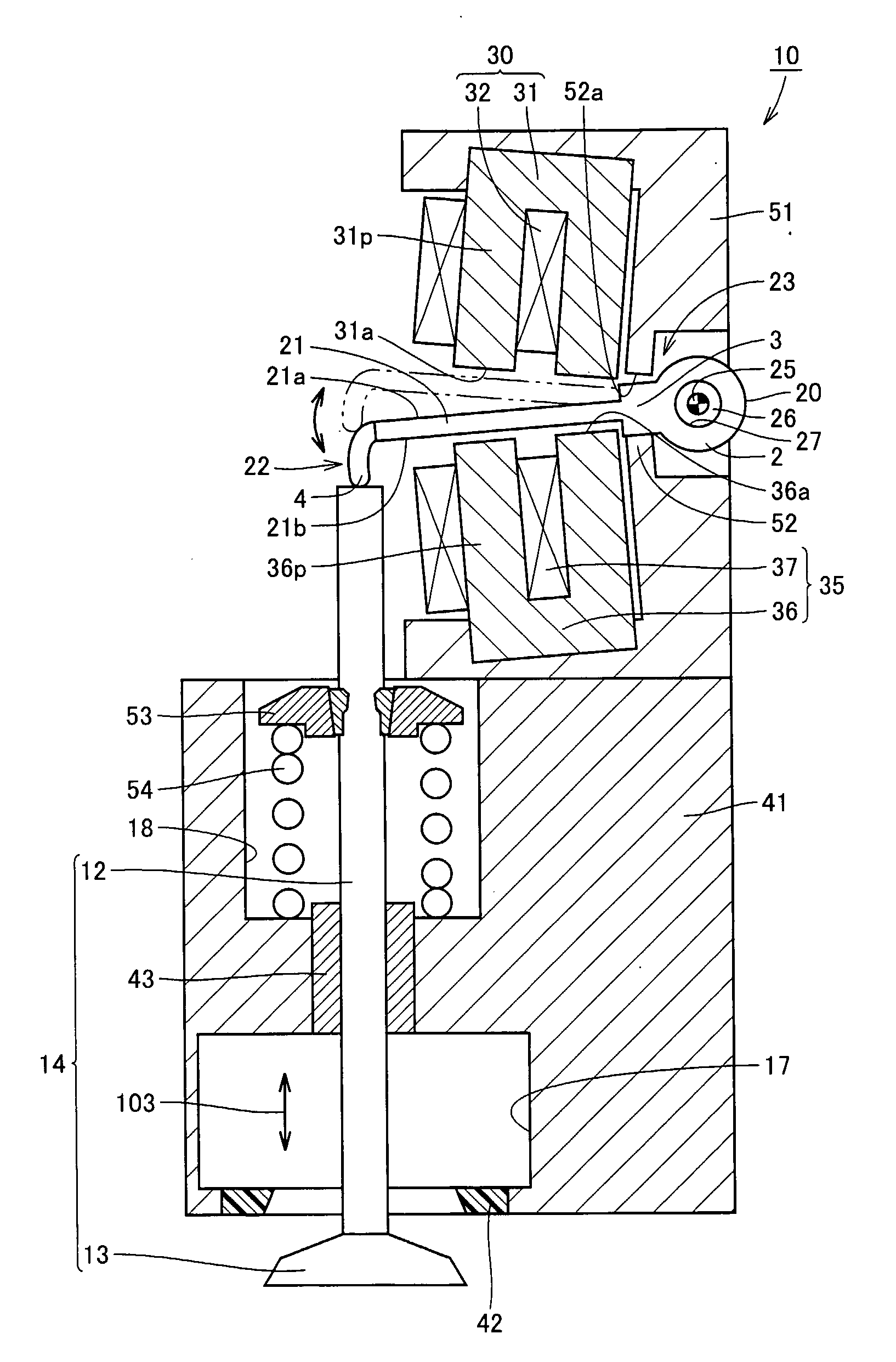
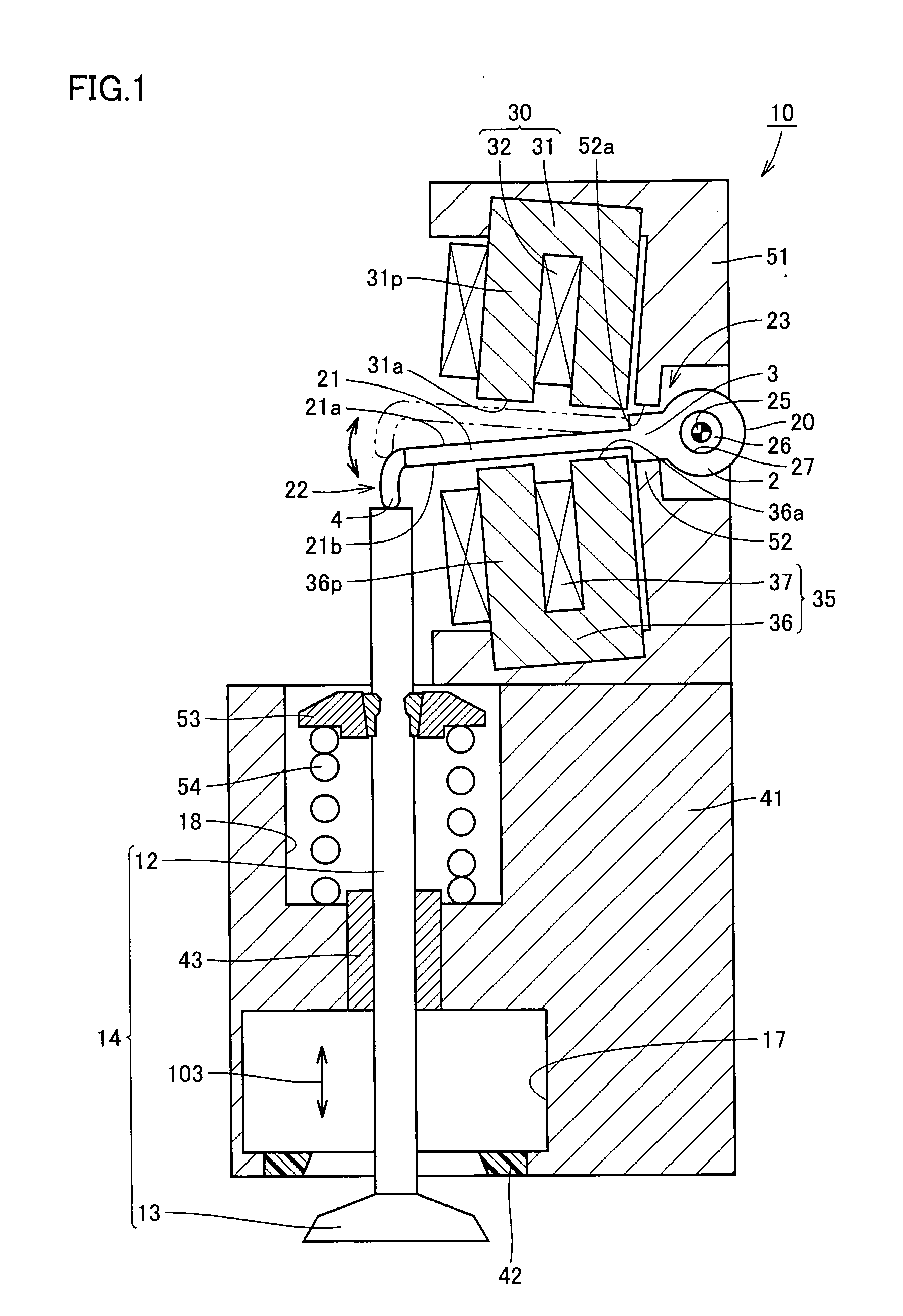
[0028] Referring to FIG. 1, an electromagnetically driven valve 10 is a rotary drive type electromagnetically driven valve. Electromagnetically driven valve 10 includes a driven valve 14 having a stem 12 extending in one direction, a disc support base 51 provided in a manner aligned with stem 12 at a position spaced apart from stem 12, a disc 20 oscillating by receiving electromagnetic force and elastic force applied thereto, electromagnets 30 and 35 arranged above and below disc 20 and generating the electromagn...

second embodiment

[0047] An electromagnetically driven valve according to the present embodiment is structured basically in a manner similar to electromagnetically driven valve 10 in the first embodiment. Therefore, description of a redundant structure will not be repeated.

[0048] Referring to FIG. 6, in the present embodiment, arm portion 21 and root portion 3 are formed from different members respectively. Disc 20 is implemented by combining these portions. Specifically, arm portion 21 is formed from a ferromagnetic material, while root portion 3 is formed from a material of high strength. Root portion 3 may be formed from a non-magnetic material. Low-carbon iron represents one example of a material for forming arm portion 21. Examples of a material for forming root portion 3 includes high-carbon iron and an iron alloy such as chromium molybdenum steel and alloy tool steel SKD (JIS code).

[0049] Referring to FIG. 7, a groove 5 is formed in an end surface of root portion 3 facing arm portion 21, and...

third embodiment

[0051] In the following, the electromagnetically driven valve according to the present embodiment will be compared with electromagnetically driven valve 10 according to the first embodiment. Description of a redundant structure will not be repeated.

[0052] Referring to FIG. 8, an electromagnetically driven valve 50 is a rotary drive type electromagnetically driven valve. As an operation mechanism for the electromagnetically driven valve, a parallel link mechanism is applied. In the present embodiment, electromagnetically driven valve 50 includes an upper disc 20m and a lower disc 20n coupled to different positions on stem 12 respectively and oscillating upon receiving electromagnetic force and elastic force, an electromagnet 60 arranged between upper disc 20m and lower disc 20n and generating the electromagnetic force, and an upper spring 26m and a lower spring 26n provided in upper disc 20m and lower disc 20n respectively and applying the elastic force to these discs. Upper disc 20...


PUM

PropertyMeasurementUnit
heightaaaaaaaaaa
thicknessaaaaaaaaaa
widthaaaaaaaaaa

Abstract

An electromagnetically driven valve includes a driven valve having a stem and carrying out reciprocating motion along a direction in which the stem extends, a disc support base having an abutment surface, a disc extending from one end coupled to the stem toward the other end supported by the disc support base so as to allow free oscillation of the disc, and an electromagnet applying electromagnetic force to the disc. The disc has a root portion formed at the other end, and an arm portion formed from the root portion to one end. The electromagnet has a surface facing the arm portion. When the disc is attracted to the electromagnet the abutment surface abuts on the root portion and a gap is created between the surface and the arm portion. With such a structure, excellent quietness and durability can be achieved and energy loss can be reduced.

Description

TECHNICAL FIELD [0001] The present invention generally relates to an electromagnetically driven valve, and more particularly to an electromagnetically driven valve of a rotary drive type used in an internal combustion engine. BACKGROUND ART [0002] As a conventional electromagnetically driven valve, for example, U.S. Pat. No. 6,467,441 specification discloses an electromagnetic actuator actuating valves of an internal combustion engine as a result of cooperation of electromagnetic force and a spring. The electromagnetic actuator disclosed in the specification is called a rotary drive type, and includes a valve having a stem and an oscillating arm having a first end hinged on a support frame and a second end in abutment on the upper end of the stem. [0003] An electromagnet consisting of a core and a coil wound around the core is arranged above and below the oscillating arm. The electromagnetic actuator further includes a torsion bar provided at the first end of the oscillating arm and...

Claims


Application Information

Patent Timeline
Patent Type & Authority Applications(United States)
IPC IPC(8): F01L9/04F01L9/20F16K31/06H01F7/14
CPCF01L9/04F01L2009/2109F01L9/20
Inventor MASAOKA, TOSHIKAASANO, MASAHIKO
Owner TOYOTA JIDOSHA KK
Why Eureka
Try Eureka