Clock signal generating apparatus and clock signal receiving apparatus

a clock signal and generating apparatus technology, applied in the direction of generating/distributing signals, instruments, pulse techniques, etc., can solve the problems of signal transmission delay, system stability degradation, signal stability degradation, etc., and achieve the effect of eliminating nois

Inactive Publication Date: 2007-07-05
SAMSUNG ELECTRONICS CO LTD +4
View PDF5 Cites 11 Cited by
  • Summary
  • Abstract
  • Description
  • Claims
  • Application Information

AI Technical Summary

Benefits of technology

[0013] A clock signal receiving apparatus according to the present invention includes an amplifier, a first input voltage adjusting unit, a second input adjusting unit, and a feedback unit. The amplifier generates an amplified signal based on an input signal of a first input end and an input signal of a second input end, and outputs the amplified signal to an output end. The first input voltage adjusting unit adjusts a voltage level of a clock signal transmitted from a clock signal generating apparatus, and provides the adjusted clock signal to the first input end. The second input voltage adjusting unit provides a source voltage divided by a voltage divider to the second input end. The feedback unit is connected between the output end and the second input end, and eliminates noise.

Problems solved by technology

Particularly, unlike clock signal transmission / receiving of a low-speed device, clock signal transmission / receiving of a high-speed device causes signal transmission delay due to a path length difference between each of clock receiving ends and the clock signal generator, and due to a timing skew caused by the signal transmission delay.
In addition, noise inflow during the high-speed clock signal transmission causes degradation of signal stability.
Accordingly, when determining a level of the received clock signal, a result value may vary depending on a sampling point, thereby causing deterioration of system stability.
Otherwise, clock jitter occurs due to noise, thereby causing system instability.

Method used


Image

  • Clock signal generating apparatus and clock signal receiving apparatus
  • Clock signal generating apparatus and clock signal receiving apparatus
  • Clock signal generating apparatus and clock signal receiving apparatus

Examples


Embodiment Construction

[0021] In the following detailed description, only certain exemplary embodiments of the present invention have been shown and described, simply by way of illustration. As those skilled in the art would realize, the described embodiments may be modified in various different ways, all without departing from the spirit or scope of the present invention. Accordingly, the drawings and description are to be regarded as illustrative in nature and not restrictive. Like reference numerals designate like elements throughout the specification.

[0022] A clock transmitting apparatus providing clock synchronization and a clock signal receiving apparatus according to an exemplary embodiment of the present invention will now be described in more detail with reference to the accompanying drawings.

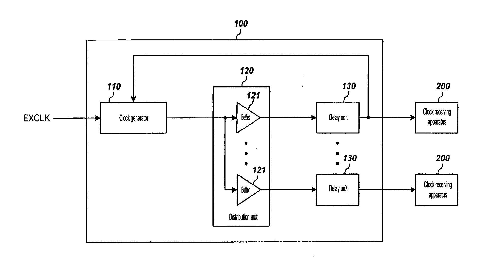
[0023]FIG. 3 is a block diagram of a click transmitting apparatus according to the exemplary embodiment of the present invention.

[0024] As shown in FIG. 3, a clock signal generating apparatus 100 includes...


PUM


Abstract

A clock signal generating apparatus including a clock generator, a distributor, a plurality of delay units, and generates a clock signal for synchronized driving of a system having a plurality of clock receiving apparatuses. The clock signal generator generates a clock signal for driving the system by using an external clock signal and a feedback clock signal. The distributor distributes the clock signal output to generate a plurality of distributed clock signals and outputs the plurality of distributed clock signals to the plurality of clock receiving apparatuses through a plurality of signal transmission paths. The plurality of delay units are respectively located on the plurality of signal transmission paths, control phases of the plurality of distributed clock signals to generate a plurality of phase-controlled clock signals, and transmit the plurality of phase-controlled clock signals to the plurality of clock receiving apparatuses.

Description

PRIORITY [0001] This application claims priority to Korean Patent Application No. 10-2005-0121366 filed in the Korean Intellectual Property Office on Dec. 10, 2005, the contents of which are incorporated herein by reference. BACKGROUND OF THE INVENTION [0002] 1. Field of the Invention [0003] The present invention relates to a clock signal generating apparatus and a clock signal receiving apparatus that have an advantage of eliminating clock signal deviation. [0004] 2. Description of the Related Art [0005] Recently, various parts that configure an electronic device have been improved in performance, and accordingly, a signal transmission speed must be guaranteed by eliminating deviation of a clock signal used for driving each part of the device through signal transmission synchronization between each part of the device to thereby improve electronic device performance. Therefore, signal synchronization for elimination of clock deviation in signal transmission between a board and a plu...

Claims


Application Information

Patent Timeline
Patent Type & Authority Applications(United States)
IPC IPC(8): G06F1/04H03K3/00
CPCG06F1/04H03K5/1565H03K5/003H03K5/125
Inventor LEE, SEOK-JINCHO, SEUNG-KWONKIM, YOUNG-IL
Owner SAMSUNG ELECTRONICS CO LTD
Why Eureka
Try Eureka