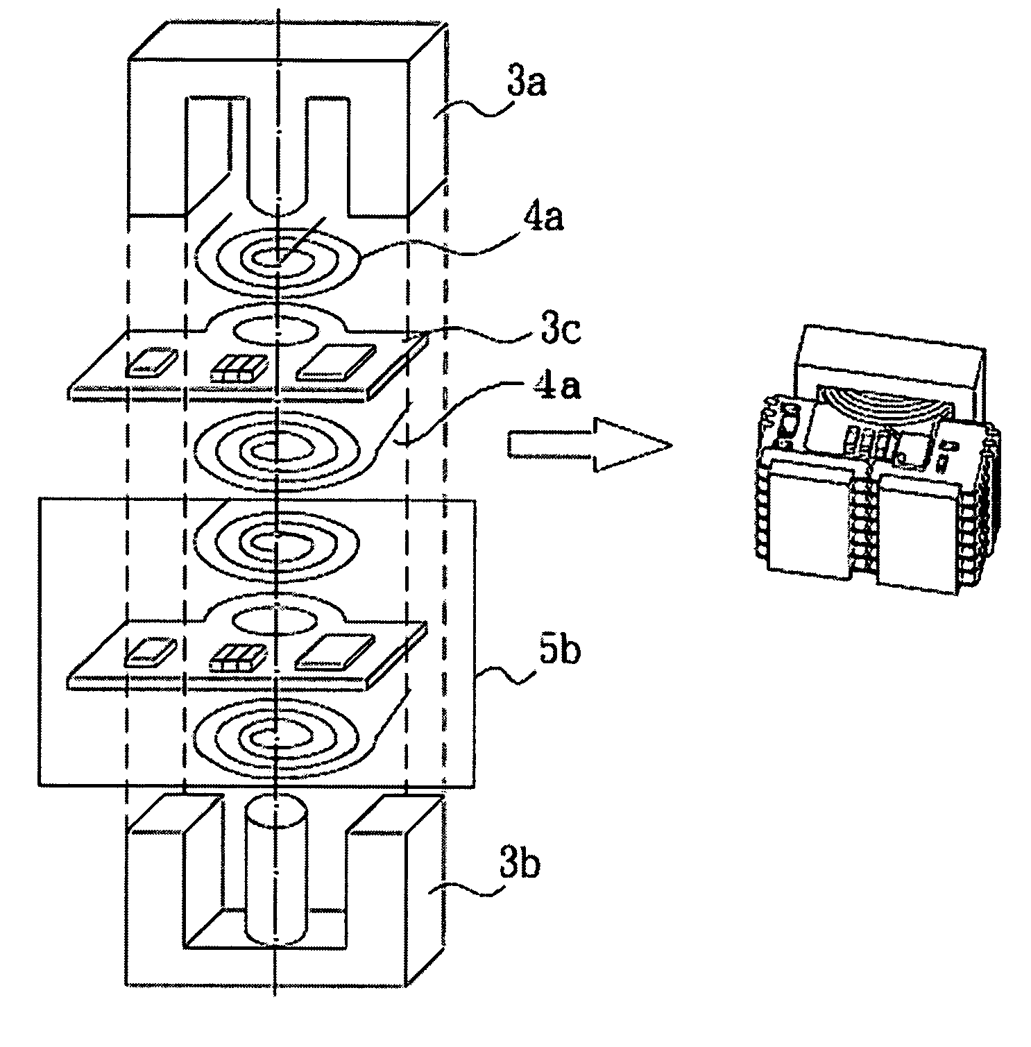
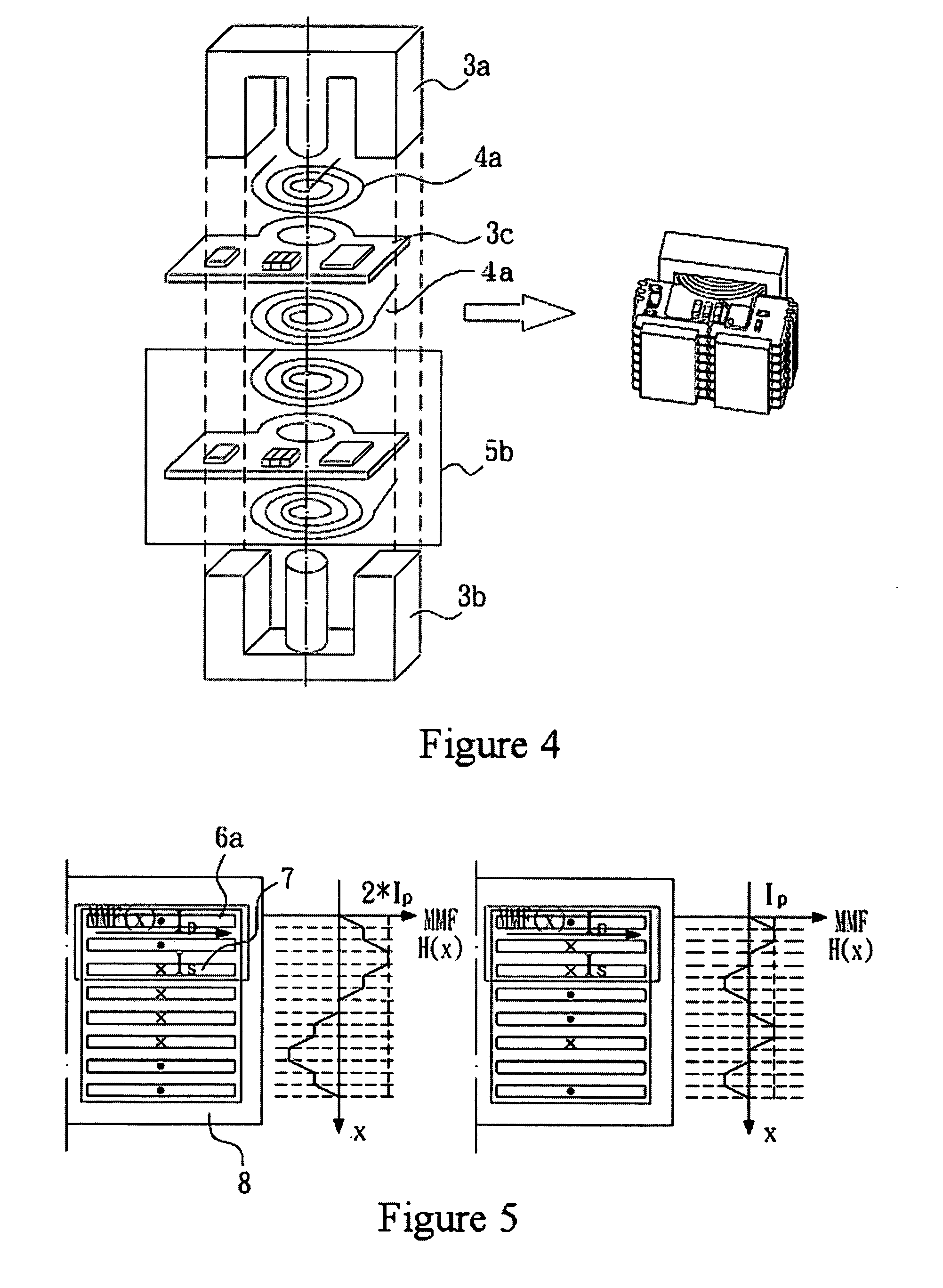
Transformer structure
a transformer and transformer technology, applied in the direction of electric variable regulation, process and machine control, instruments, etc., can solve the problems of increasing the terminal power loss of the output windings of the conventional large power transformer b>1/b>, affecting the reliability and efficiency of the circuit, and increasing the power loss of the transformer winding itself. , to achieve the effect of enhancing the efficiency of the whole circuit, reducing the length of ac wires and transformer wear
- Summary
- Abstract
- Description
- Claims
- Application Information
AI Technical Summary
Benefits of technology
Problems solved by technology
Method used
Image

Examples
Embodiment Construction
[0041] Several embodiments of the present invention are described in detail below. However, the invention can be widely implemented in other embodiments besides the detailed embodiments, and the invention is not limited to the following embodiments except as by the appended claims.
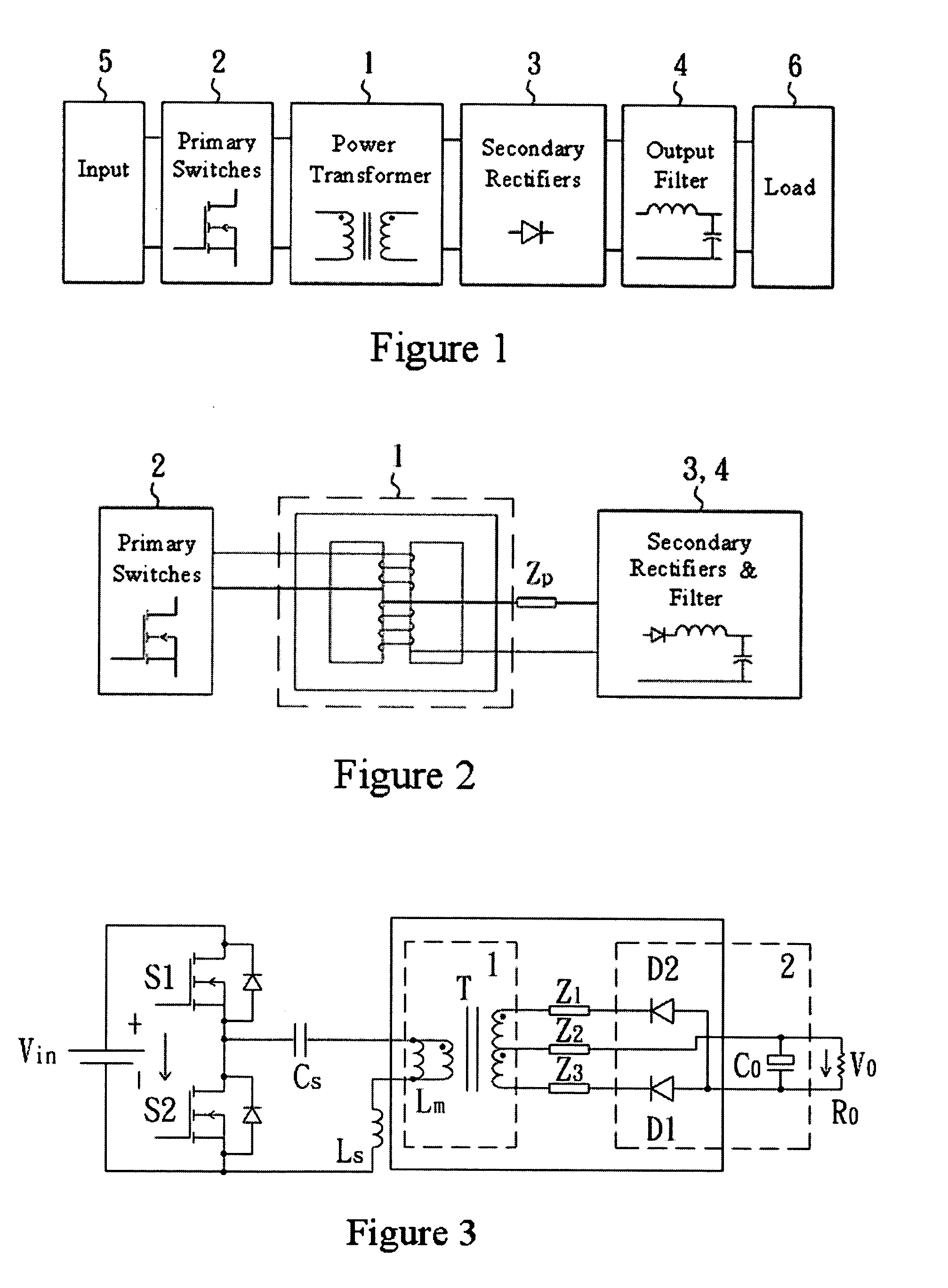
[0042] Referring now to the drawings wherein the showings are for the purposes of illustrating a preferred embodiment of the invention only and not limiting the invention. A structure diagram of a half-bridge LLC series resonant circuit is shown in FIG. 3, illustrating an integrated output rectifier unit (including an output filtering capacitor) of a secondary side of a transformer. The transformer structure of the invention can be applied to high power transformers and to other power range transformers as well. In general, an inductor (Ls), a capacitor (Cs), and a magnetizing inductor (Lm) of the transformer form a LLC resonant circuit. Two main switches S1 and S2 form a half-bridge structure to achieve ...
PUM
 Abstract
Description
Claims
Application Information