Liquid crystal display

Inactive Publication Date: 2007-07-05
DAI NIPPON PRINTING CO LTD
View PDF10 Cites 3 Cited by
  • Summary
  • Abstract
  • Description
  • Claims
  • Application Information

AI Technical Summary

Benefits of technology

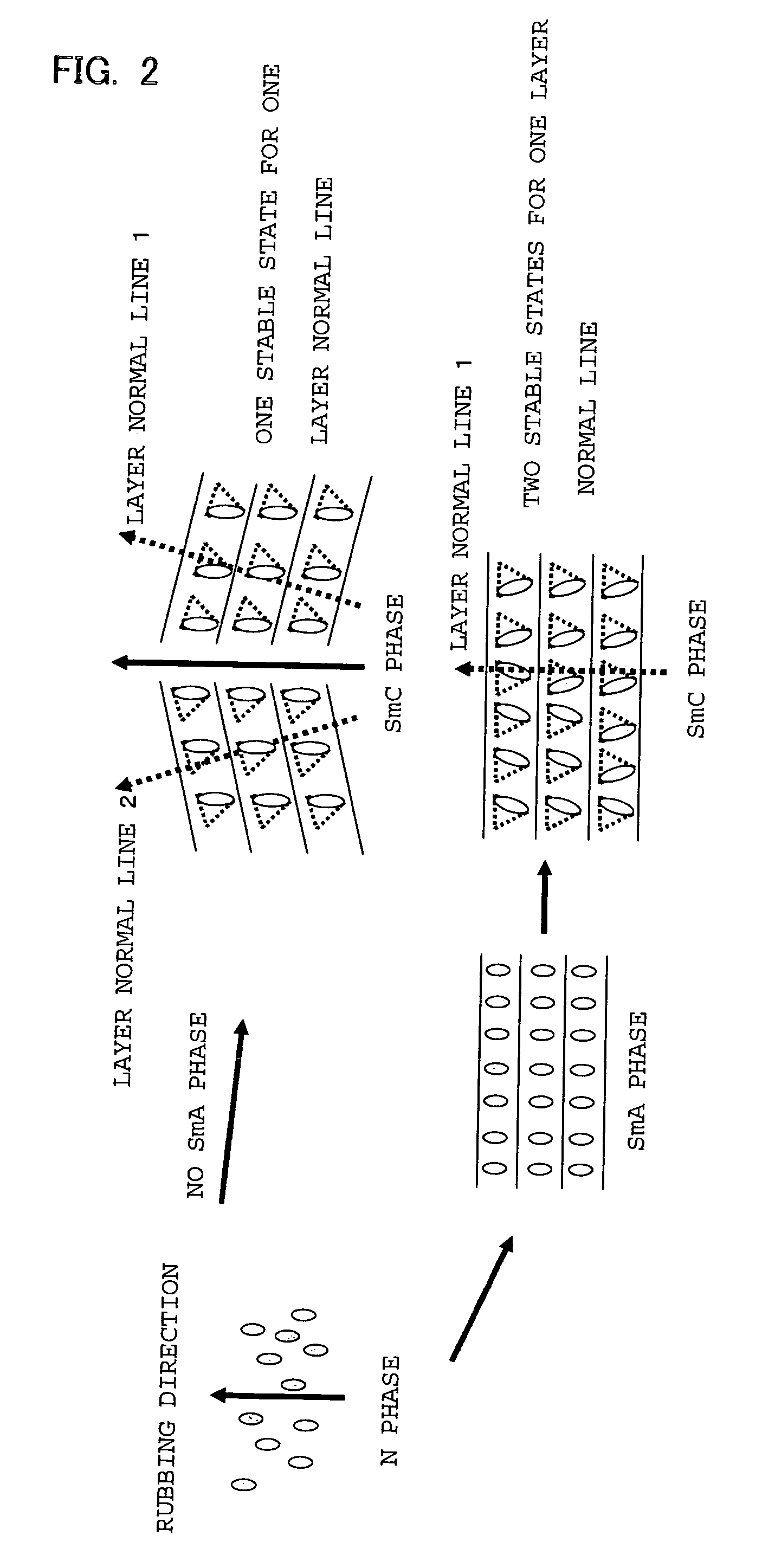
[0024] The ferroelectric liquid crystal is preferably a ferroelectric liquid crystal having, in a phase series thereof, no smectic A phase. As described above, the ferroelectric liquid crystal having, in the phase series thereof, no smectic A phase easily generates alignment defects such as double domains. However, when the compositions of the upper and lower photo alignment layers, which sandwich the ferroelectric liquid crystal, are made different from each other, alignment defects such as double domains can be restrained from being generated so that the advantageous effects resulting from the structure of the present invention become remarkable.
[0025] The ferroelectric liquid crystal is preferably a ferroelectric liquid crystal which constitutes a single phase. This is because the liquid crystal display of the present invention provides the following advantages: a preferable alignment can be obtained even with a single phase ferroelectric liquid crystal, without the need of using a method such as a polymer stabilizing method for controlling the alignment, so as to facilitate the production process easily while lowering the driving voltage.
[0026] The liquid crystal display is preferably driven by an active matrix system using a thin film transistor. This is because the adoption of the active matrix system using TFT elements makes it possible to switch on or off target pixels surely to give high-quality display. Furthermore, it is possible to c

Problems solved by technology

However, since nematic liquid crystal is used therein, the response speed of the liquid crystal material is as small as several milliseconds to several tens of milliseconds and it cannot be said that these sufficiently cope with display of moving images.
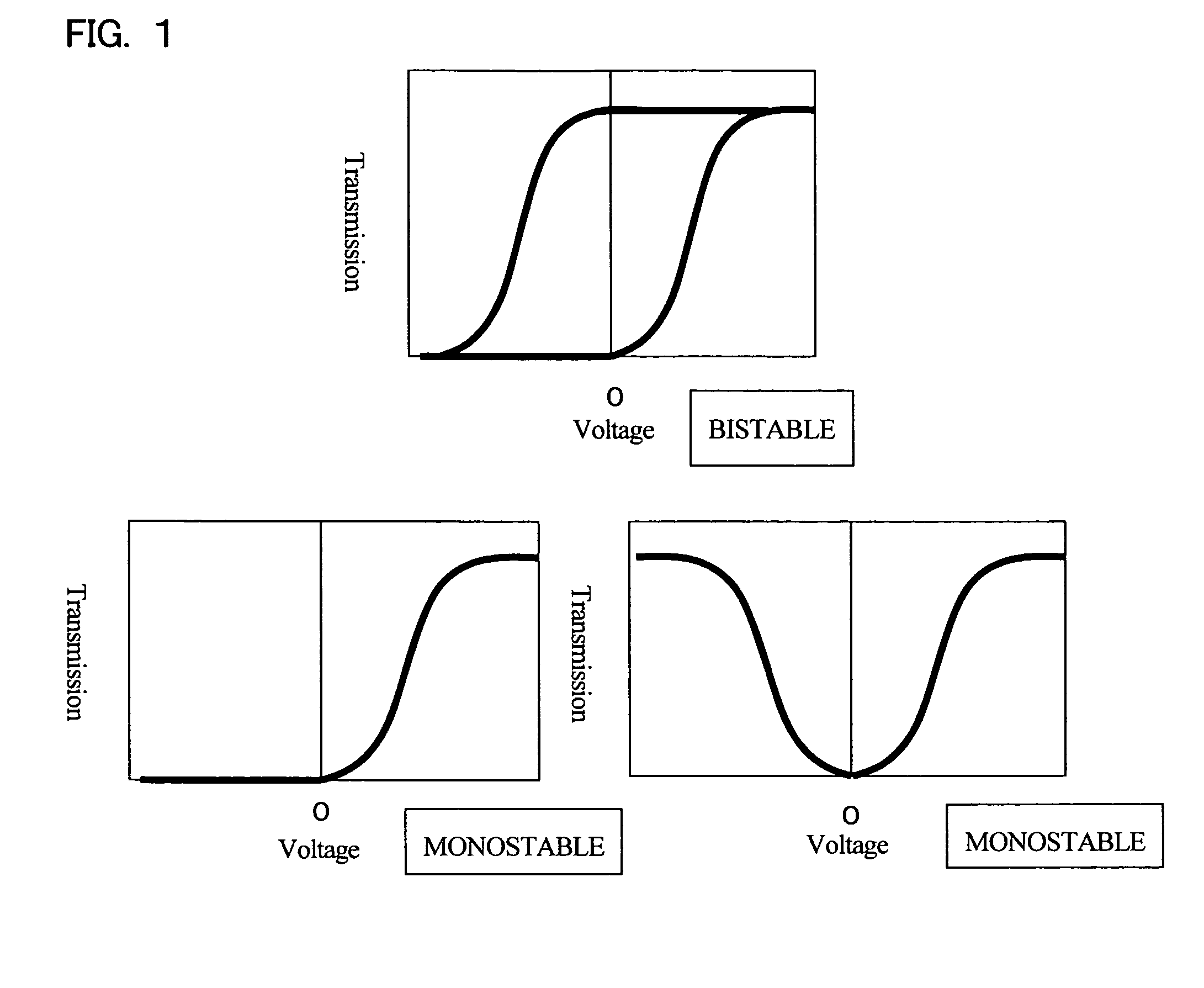
However, the liquid crystal has a problem that the liquid crystal has memory property but gray scale display cannot be attained since the switching thereof is limited to two states, namely, bright and dark states.
On the other hand, ferroelectric liquid crystal has a higher order of molecules therein than nematic liquid crystal; therefore, the former liquid crystal is not easily aligned so that defects called zigzag defects or hairpin defects are easily generated.
Such defects cause a fall in contrast based on light leakage.
This method has problems that the alignment of the liquid crystal is disturbed when the temperature thereof is again raised to a temperature not lower than the phase transition temperature thereof and the alignment is disturbed in regions where no electric field acts between pixel electrodes, and other problems.
However, this method has the following problems: the generatio

Method used


Image

  • Liquid crystal display
  • Liquid crystal display
  • Liquid crystal display

Examples


Example

Example 1

[0099] Two glass substrates each coated with ITO were spin-coated with a 1% by weight solution of the compound 1 dissolved in N-methyl-2-pyrrolidinone and 2-n-butoxyethanol (50:50% by weight) and a 1% by weight solution of the compound 5 dissolved in N-methyl-2-pyrrolidinone and 2-n-butoxyethanol (50:50% by weight) at a rotation frequency of 4000 rpm for 30 seconds. The substrate spin-coated with the solution of the compound was dried at 100° C. in an oven for 1 minute, and then polarized ultraviolet rays were radiated onto the substrate at 1000 mJ / cm2 and at 25° C. Furthermore, the one having the solution of the compound 5 spin-coated was heated at 150° C. under the atmosphere of nitrogen for 1 hour after the exposure. Spacers of 1.5 μm size were sprayed onto one of the substrates, and a sealing material was applied onto the other substrate with a seal disperser. Thereafter, the substrates were fabricated in parallel to the radiation direction of the polarized ultraviolet...

Example

Comparative example 1

[0100] Two glass substrates each coated with ITO were spin-coated with a 1% by weight solution of the compound 1 dissolved in N-methyl-2-pyrrolidinone and 2-n-butoxyethanol (50:50% by weight), at a rotation frequency of 4000 rpm for 30 seconds. Thereafter, they were dried and subjected to exposure treatment in the same manner as in Example 1, thereafter, the resultant was heated at 150° C. under the atmosphere of nitrogen for 1 hour. Furthermore, they were fabricated into a cell by the above-mentioned method, and then the liquid crystal was injected thereinto. As a result, no mono-domain phase was obtained, and alignment defects such as double domains, zigzag defects and hairpin defects were generated.

Example

Comparative example 2

[0101] Two glass substrates each coated with ITO were spin-coated with a 1% by weight solution of the compound 5 dissolved in N-methyl-2-pyrrolidinone and 2-n-butoxyethanol (50:50% by weight), at a rotation frequency of 4000 rpm for 30 seconds. Thereafter, they were dried and subjected to exposure treatment in the same manner as in Example 1, thereafter, the resultant was heated at 150° C. under the atmosphere of nitrogen for 1 hour. Furthermore, they were fabricated into a cell by the above-mentioned method, and then the liquid crystal was injected thereinto. As a result, no mono-domain phase was obtained, and alignment defects such as double domains, zigzag defects and hairpin defects were generated.


PUM


Abstract

A liquid crystal display using a ferroelectric liquid crystal, which can give mono-domain alignment of the ferroelectric liquid crystal without forming alignment defects such as zigzag defects, hairpin defects and double domains and which is so remarkably good in alignment stability that the alignment thereof can be maintained even if the temperature of the liquid crystal is raised to the phase transition point or higher. The liquid crystal display has a ferroelectric liquid crystal sandwiched between two substrates, wherein an electrode and a photo alignment layer are each successively formed on opposite faces of the two substrates facing each other, and a constituent material of the respective photo alignment layer has a different composition with the ferroelectric liquid crystal sandwiched therebetween.

Description

TECHNICAL FIELD [0001] The present invention relates to a liquid crystal display using ferroelectric liquid crystal, more specifically, a liquid crystal display in which a photo alignment layer is used to control the alignment of ferroelectric liquid crystal. BACKGROUND ART [0002] Since liquid crystal displays have features that it is thin and is low in power consumption and other features, the use thereof has been expanding in various articles from large-sized displays to portable information terminals and the development thereof has been actively made. Conventionally, for liquid crystal displays, a TN system, an STN multiplex driving system, an active matrix driving system in which thin film transistors (TFTs) are used in TN, and others have been developed and made practicable. However, since nematic liquid crystal is used therein, the response speed of the liquid crystal material is as small as several milliseconds to several tens of milliseconds and it cannot be said that these ...

Claims


Application Information

Patent Timeline
IPC IPC(8): C09K19/52C09K19/00G02F1/141G02F1/133G02F1/1337
CPCG02F1/1337G02F1/133788Y10T428/10G02F2001/133773Y10T428/1005G02F1/141C09K2323/00C09K2323/02G02F1/133773C09K19/56G02F1/133
Inventor SAWATARI, NAOKOOKABE, MASATOHAMA, HIDEO
Owner DAI NIPPON PRINTING CO LTD
Why Eureka
Try Eureka