Time-resolved non-invasive optometric device for medical diagnostic

a non-invasive, optometric technology, applied in the field of non-invasively probing the inner structure of the skin of a patient, can solve the problems of limiting the effectiveness of the above-mentioned device, inconvenient use, and inability to accurately detect the inner structure of the skin of the patient,

Inactive Publication Date: 2007-07-05
RGT UNIV OF CALIFORNIA
View PDF28 Cites 37 Cited by
  • Summary
  • Abstract
  • Description
  • Claims
  • Application Information

AI Technical Summary

Benefits of technology

[0029] In some embodiments, the compared fluorescence signal may be used to monito...

Problems solved by technology

However, the vast majority of the human subjects were Caucasian, and measurements were performed only on the patient's forearm.
Moreover, steady-state fluorescence techniques of the above device have several disadvantages that limit their effectiveness: 1) they cannot distinguish fluorophores emitting at similar wavelengths; 2) they are influenced by endogeneous chromophores, which interact with the excitation and fluorescent light; and 3) the fluorescence signal depends on the geometry and the probe design, and the properties of the skin such as pigmentation....

Method used


Image

  • Time-resolved non-invasive optometric device for medical diagnostic
  • Time-resolved non-invasive optometric device for medical diagnostic
  • Time-resolved non-invasive optometric device for medical diagnostic

Examples


Embodiment Construction

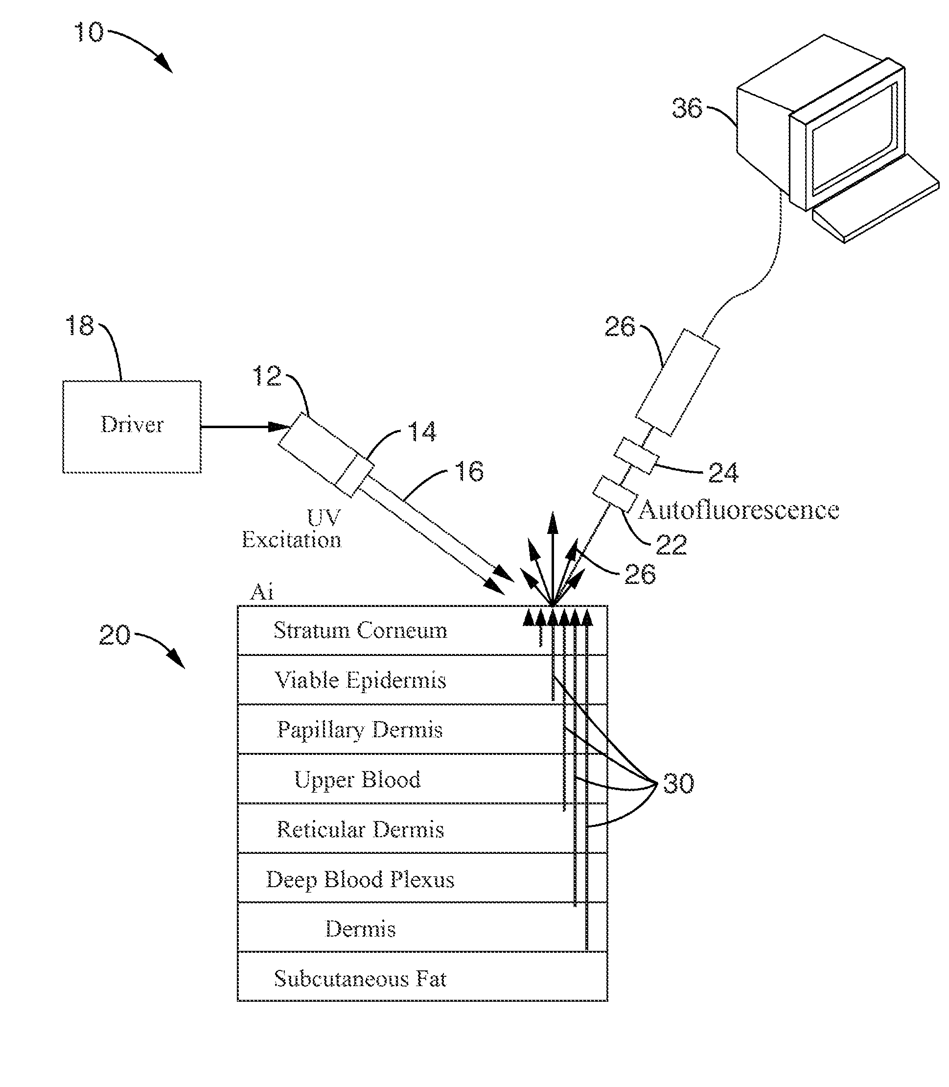
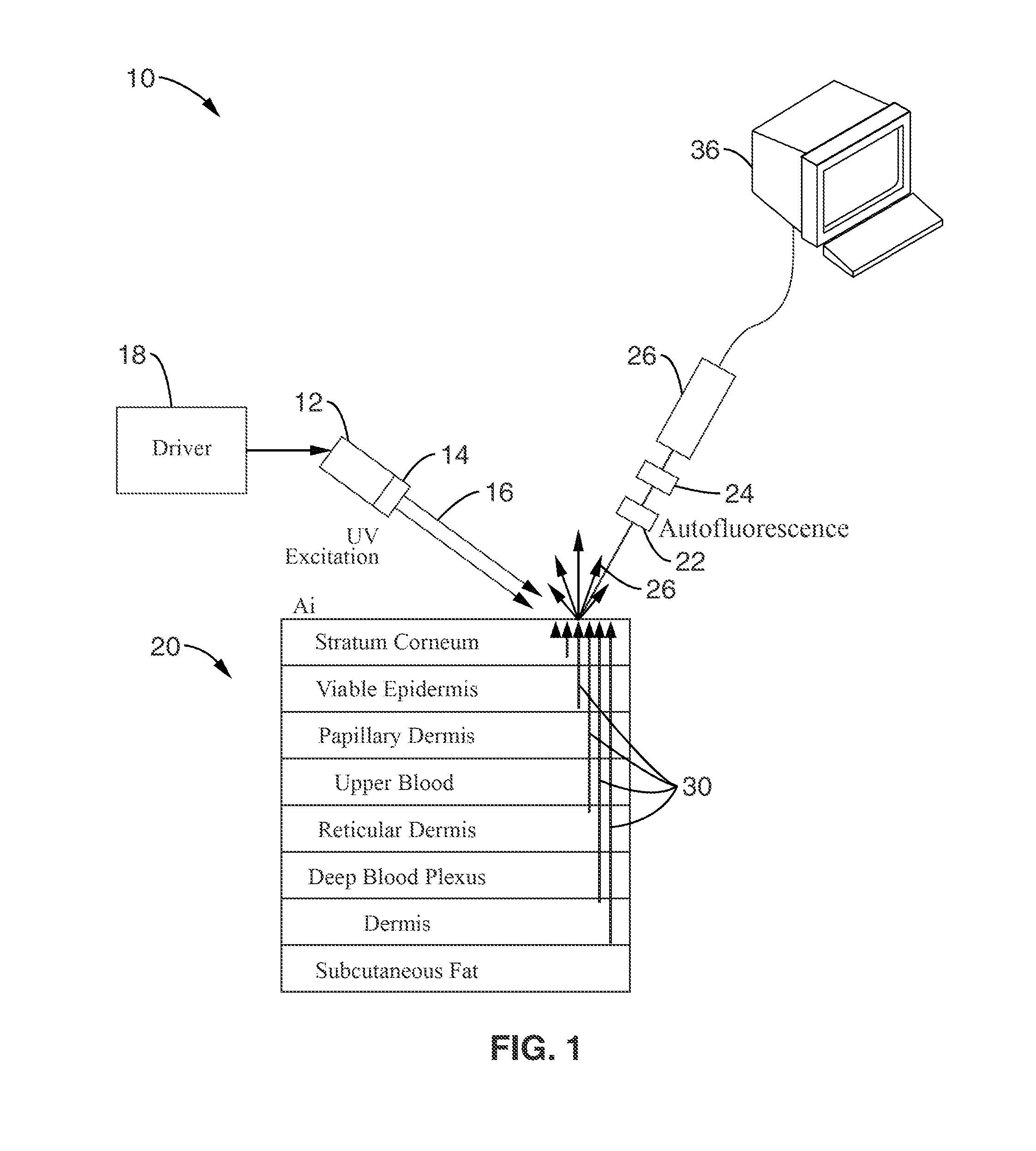
[0061] Referring more specifically to the drawings, for illustrative purposes the present invention is embodied in the apparatus generally shown in FIG. 1 through FIG. 15. It will be appreciated that the apparatus may vary as to configuration and as to details of the parts, and that the method may vary as to the specific steps and sequence, without departing from the basic concepts as disclosed herein.

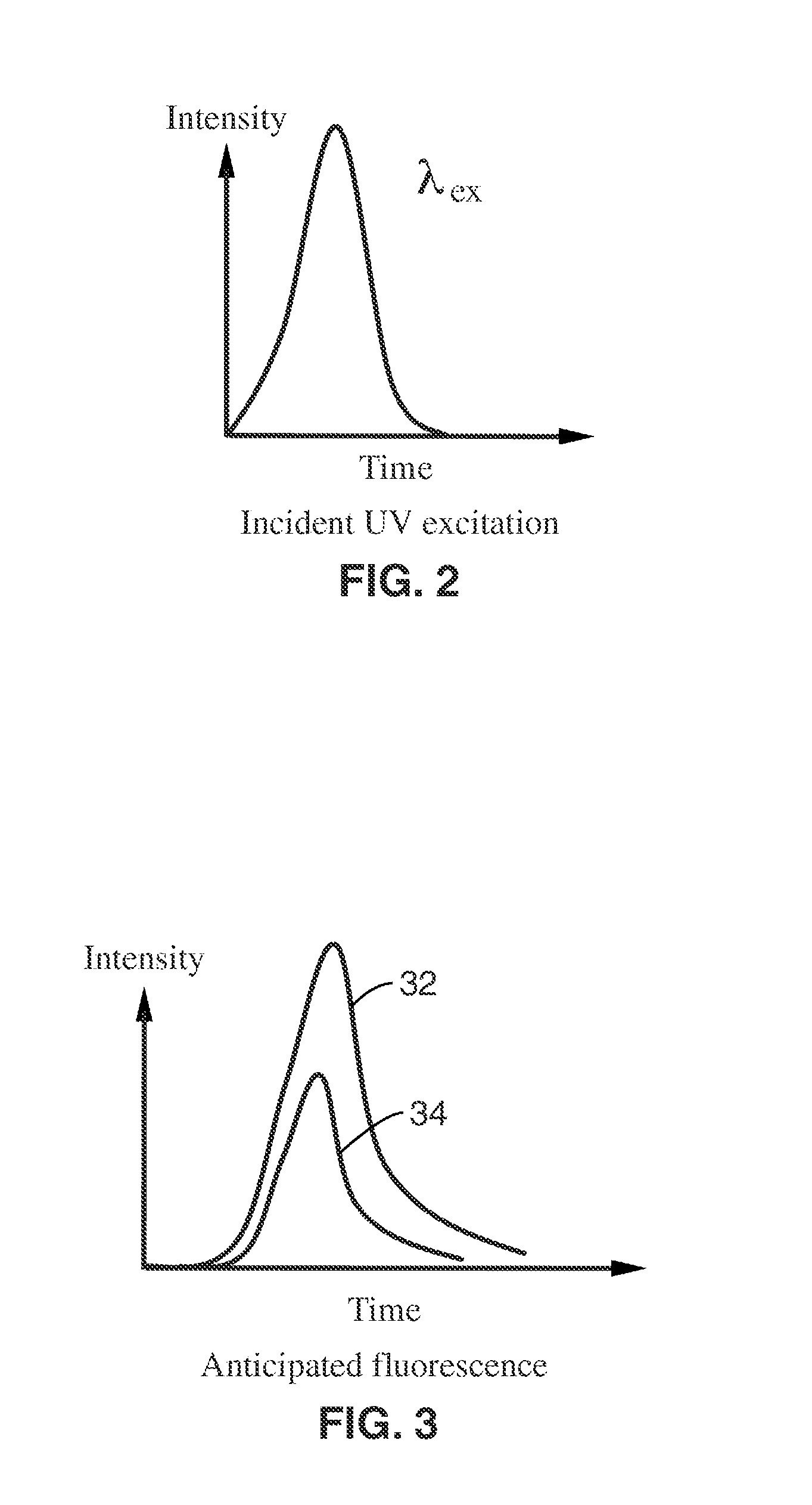
[0062] Many health conditions affect the morphology, physiology, and fluorescence characteristics of the human skin. Therefore, light transport, and in particular transient light transport and time-resolved fluorescence within the skin, differ from healthy subjects to patients with targeted disorders.

[0063] For example, presence of diabetes mellitus is generally associated with measurably thickened skin and yellow hue among diabetic patients compared with their non-diabetic counterparts. In addition to pre-diagnostic of diabetes, time-resolved fluorescence spectroscopy of skin couple...


PUM


Abstract

A time-resolved fluorescence device is described for the detection and diagnosis of various metabolic diseases in a noninvasive or minimally invasive manner. The device uses an ultra-short excitation pulse that comprises of a repetition of nanosecond pulses. The excitation pulse is directed incident onto a strategically selected area of the patient body such as the forearm, the feet, and the palm. This light interacts with the different layers of the skin. The absorbed light excites conditions of interest in the skin, which in turn generate a fluorescence signal, which is collected by a detector. A processor is coupled to the detector to measure the transient fluorescence intensity decay of the skin in terms of lifetimes, and the contribution of individual fluorophores to the overall fluorescence signal.

Description

CROSS-REFERENCE TO RELATED APPLICATIONS [0001] This application claims priority from, and is a 35 U.S.C. § 111(a) continuation of, co-pending PCT international application serial number PCT / US2005 / 021594, filed on Jun. 17, 2005, incorporated herein by reference in its entirety, which claims priority from U.S. provisional application Ser. No. 60 / 581,151, filed on Jun. 17, 2004, herein incorporated by reference in its entirety. [0002] This application is related to PCT International Publication Number WO / 2006 / 009910 A2, herein incorporated by reference in its entirety, and to PCT International Publication Number WO / 2006 / 009906 A2, herein incorporated by reference in its entirety.STATEMENT REGARDING FEDERALLY SPONSORED RESEARCH OR DEVELOPMENT [0003] Not Applicable INCORPORATION-BY-REFERENCE OF MATERIAL SUBMITTED ON A COMPACT DISC [0004] Not Applicable NOTICE OF MATERIAL SUBJECT TO COPYRIGHT PROTECTION [0005] A portion of the material in this patent document is subject to copyright prot...

Claims


Application Information

Patent Timeline
IPC IPC(8): A61B5/00
CPCA61B5/0059G01N2800/04A61B5/14532A61B5/1455A61B5/443A61B5/444A61B5/6816A61B5/6824A61B5/6825A61B5/6829G01N21/4795G01N21/6408G01N21/6428G01N21/6486G01N33/6881G01N33/6893G01N2021/6421G01N2021/6491A61B5/0071
Inventor PILON, LAURENT G.KATIKA, KAMAL M.
Owner RGT UNIV OF CALIFORNIA
Why Eureka
Try Eureka