
Rod Type Mechanical Valve for Fluid Flow Control

Inactive Publication Date: 2007-07-12
MITCHELL GEORGE D +1
View PDF17 Cites 0 Cited by
  • Summary
  • Abstract
  • Description
  • Claims
  • Application Information

AI Technical Summary

Benefits of technology

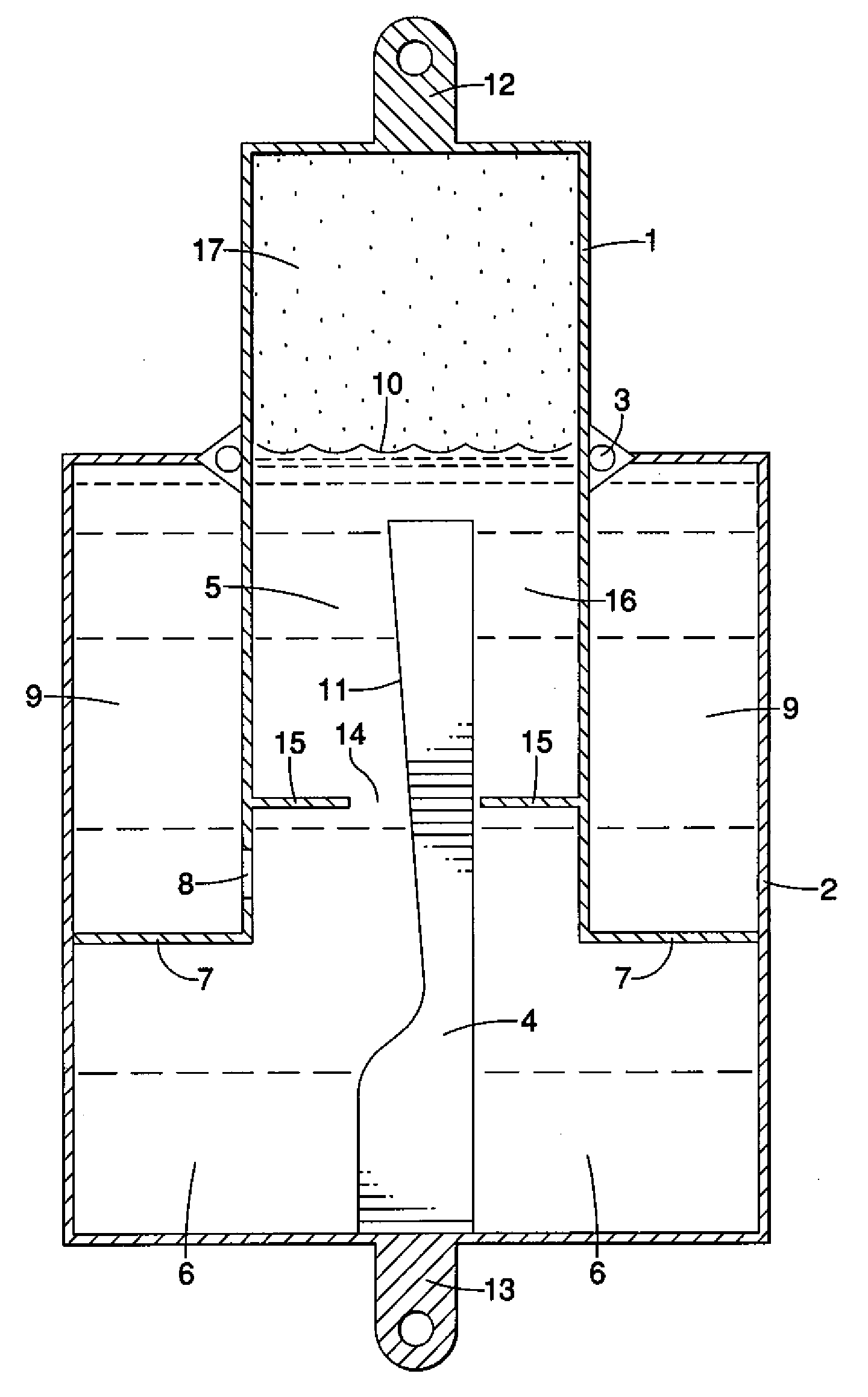
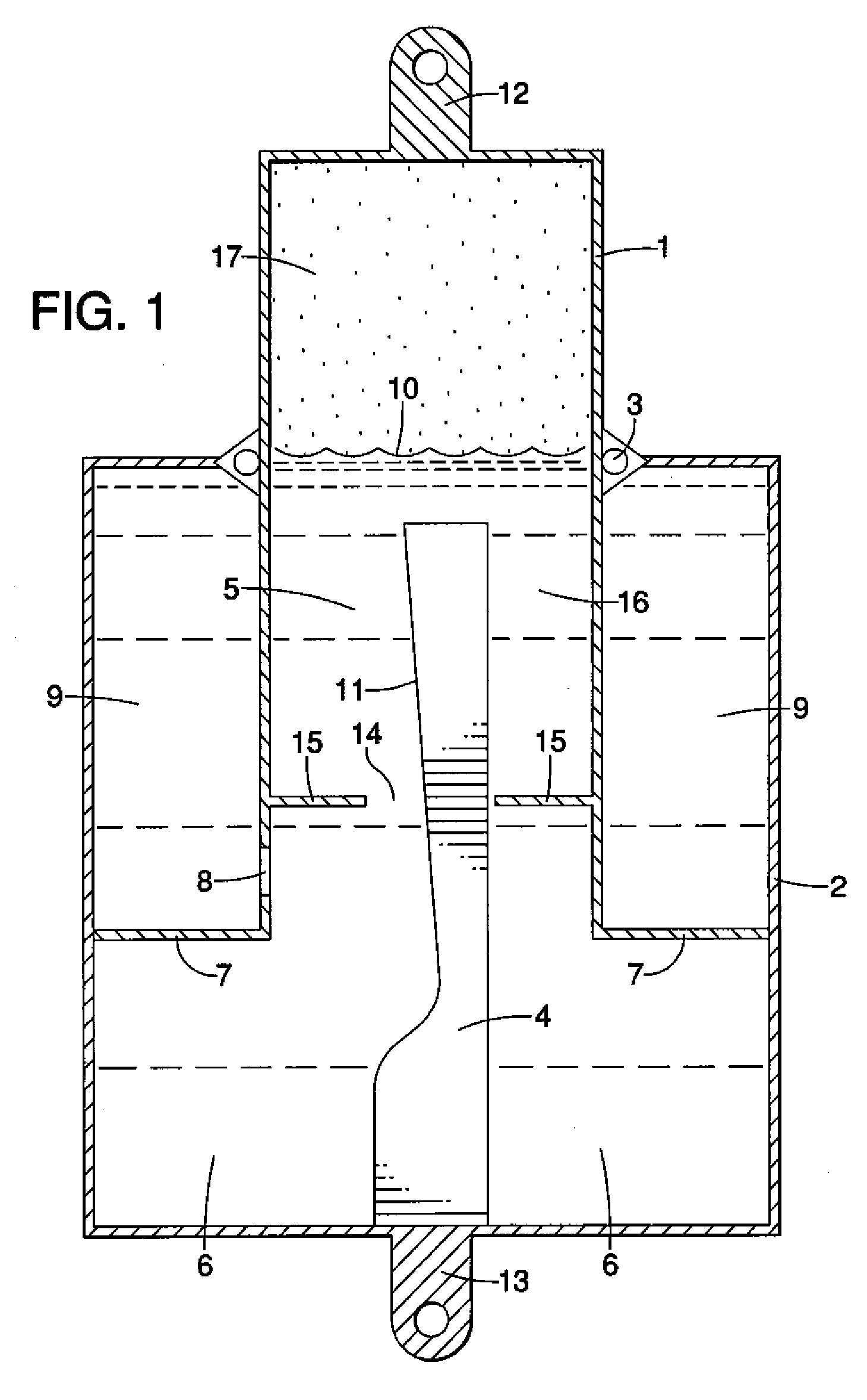
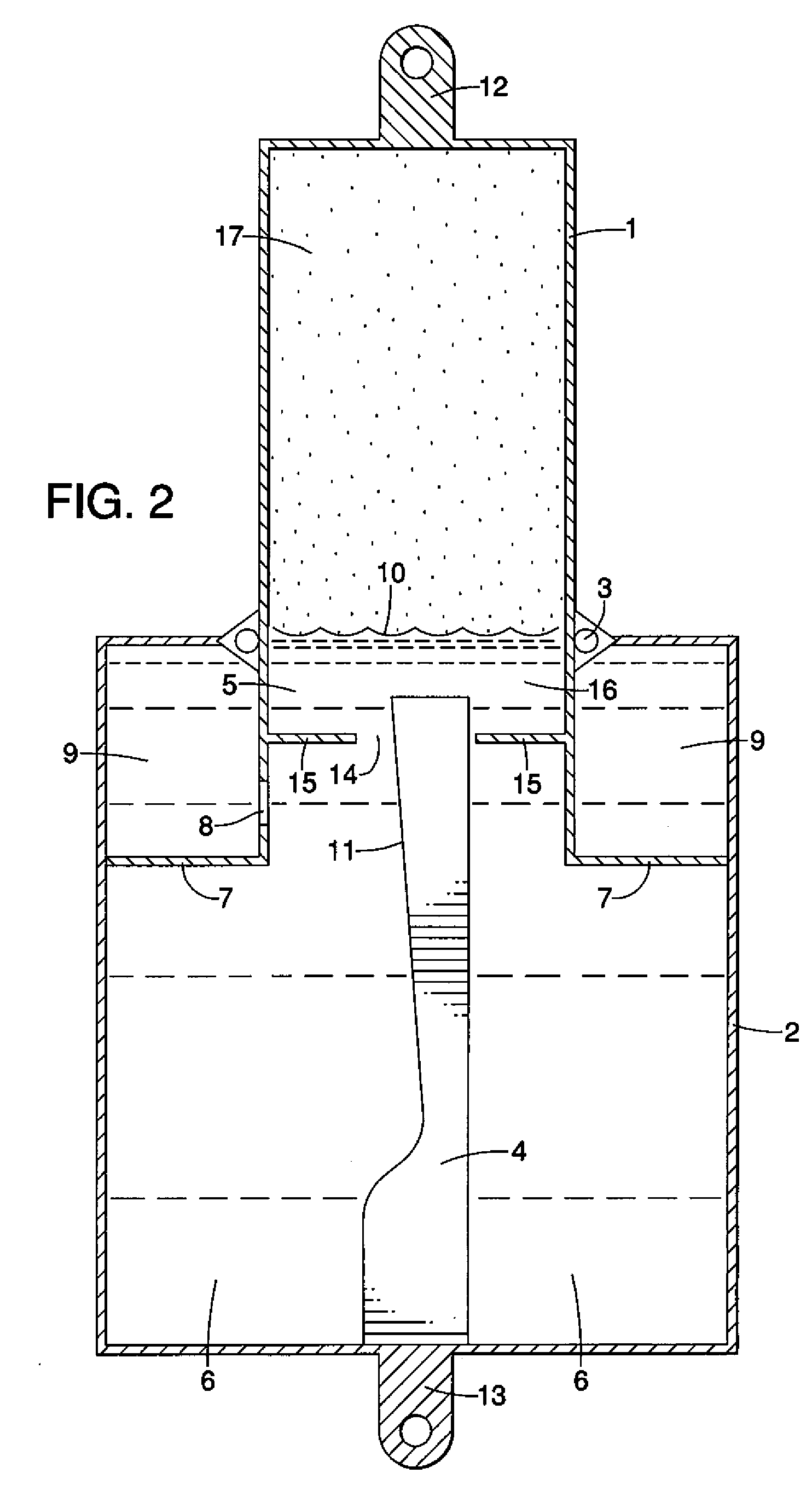
[0018] In a preferred embodiment of the present invention, the rod and orifice mechanical fluid flow control valve is utilized in a motion restriction device, namely an automotive shock absorber. Such an embodiment typically exhibits desirable performance, adjustability, consistency or reliability over traditional shock absorbers that utilize a traditional clapper valve.
[0019] According to one aspect of the invention, a motion restriction device having a piston and a cylinder utilizes a rod and orifice valve to control the flow of fluid between two or more pressure areas to control acceleration between the piston and the cylinder. More particularly, the rod can be configured with a custom shape adapted to the specific application, thereby creating an intended response of the motion restriction device to various dynamic motions between the piston and the cylinder. By way of example, a concave shape of the rod provides minimal motion restriction when the middle of the rod is in the orifice, while providing substantially increasingly aggressive motion restriction when one of the ends of the rod are in the orifice.
[0020] According to another aspect of the invention, embodiments can also be used to control recoil on a gun or other artillery device. In such an application, the amount of recoil energy is dependent on the explosive charge used to propel the projectile selected. Embodiments of the present invention can permit the response and stiffness of the recoil to be quickly adjusted to fit each situation, thereby preventing undesirable recoil that could affect the correct aiming of the following round.
[0022] According to yet another aspect of the invention, the rod utilized in the mechanical fluid flow control valve possesses a rectangular cross section. Such a rod is easily and highly adjustable, as the rectangular shape can be easily modified with standard workshop tools.

Problems solved by technology

Unfortunately, clapper valves and other mechanical gate valves are restricted to a limited range of operations and normally attempt to control differential pressure at some specific preset value.
When these systems are preset to some specific pressure and fluid flow rate range where they achieve best performance, they fail to properly control fluid pressure over a broader range of pressures or flow rates.
As such, these motion restriction devices also inherit the shortcomings of their basic component, the clapper valve, and translate to an inability to perform consistently and reliably over a broad range of pressures, flow rates and environmental conditions.
An example of this failure to perform is noted in ground vehicle wheel shock absorbers where axle springs or gas bag suspension systems are involved.
These devices are thus found lacking when a pothole or large bump is encountered on the traveling surface that causes wheel acceleration rates and thus shock absorber internal pressures and fluid flow rates to be excessively high, which in turn causes extreme activation or failure of the vehicle's suspension system if the shock absorber does not perform properly.
Due to the extreme dynamic motion demands placed on shock absorbers and other motion restriction devices, shock absorbers based on clapper valve technologies exhibit a substantial amount of heat generation.
This generation of heat, in turn, exacerbates and adversely affects the shock absorber's ability to perform consistently and reliably in its function of restricting the dynamic motion between two physical structures, such as a vehicle's frame and its axle.
In a traditional shock absorber, a clapper valve can only perform within a narrow range of pressures and flow rates, and the resistance is not configurable or adjustable across the stroke of the shock absorber.
This is not necessarily desirable, in terms of performance, as it places unnecessary motion restriction on the vehicle suspension system in the center of its stroke.
However, such shock absorbers are not very adjustable, and further continue to generate heat causing adverse performance conditions.
While rod and orifice mechanical valves have been available in specific applications, such as aircraft wheel struts, this technology has not yet been developed to its potential by automotive, aviation and other industries, as this technology poses significant challenges in design and manufacture.
Moreover, prior art valves are extremely difficult to precisely adjust or alter in order to change the relationship between the rod, orifice, and opening, without adversely affecting the durability of the motion restriction device.
Given the above problems caused by clapper valves and other traditional mechanical fluid flow control valves, new technologies and advancements in rod and orifice mechanical fluid flow control valves are badly needed.

Method used


Image

  • Rod Type Mechanical Valve for Fluid Flow Control
  • Rod Type Mechanical Valve for Fluid Flow Control
  • Rod Type Mechanical Valve for Fluid Flow Control

Examples


examples

[0086] In a recent experiment conducted by the inventors in Barstow, Calif., U.S.A., several embodiments of the present invention, (hereinafter the “new shock absorbers”), were compared against well-known expensive racing shock absorbers, (hereinafter referred to as the “control shock absorbers”), which are presently marketed by a leading manufacturer.

[0087] The physical dimensions of the shock absorbers were identical at 14 inches long with a 2.5 inch diameter. The control shock absorbers weighed 17 pounds each, plus the additional weight of a nitrogen tank and hose. It was necessary for the nitrogen tank to be installed at an elevation above the control shock absorbers on the vehicle. By comparison, the new shock absorbers weighed only 10 pounds and did not require any special installation considerations.

[0088] Following each vehicle's run of the course, the temperature of both sets of shock absorbers were taken by a laser thermometer and recorded. In sum, the control shock abso...


PUM


Abstract

A rod and orifice mechanical fluid flow control valve for controlling fluid flow between two or more fluid pressure areas. In another aspect, a rod and orifice mechanical fluid flow control valve for controlling or restricting the motion of two fluid pressure areas or physical structures. A motion restricting embodiment is described in detail, namely an automotive shock absorber. In another aspect, the rod in a rod and orifice mechanical fluid flow control valve is adjustable and configurable for a given application. In yet another aspect, the cross section of the rod in a rod and orifice mechanical fluid flow control valve is of a rectangular shape.

Description

CROSS REFERENCE TO RELATED APPLICATIONS [0001] This application claims the benefit of U.S. Provisional Application No. 60 / 757,391, filed Jan. 10, 2006, titled “Rod type mechanical valve for fluid control” and whose entire contents are hereby incorporated by reference.TECHNICAL FIELD [0002] The present invention pertains to rod and orifice type mechanical valve for fluid flow control. In one family of embodiments, the fluid flow control of the valve serves to manipulate or restrict the pressure differential between two separate fluid pressure areas, which can be used to control the spatial positioning or dynamic motion between two physical objects, (e.g. a shock absorber). In a wholly different family of embodiments, the spatial positioning of two physical objects or the pressure differential between two fluid pressure areas, by virtue of the valve, can be used to control a fluid flow, (e.g. an automatic irrigation valve). BACKGROUND [0003] Mechanical, automatic pressure regulating v...

Claims


Application Information

Patent Timeline
IPC IPC(8): F16K7/04
CPCF16F9/063F16F9/486G05D7/0146F16K29/00F16K13/00
Inventor MITCHELL, GEORGE D.ANDERSON, RODNEY D.
Owner MITCHELL GEORGE D
Learn More