Electron beam lithography apparatus

a lithography and electron beam technology, applied in the field of electron beam lithography apparatus, can solve the problems of distorted circle shape, land section exposed, line not connecting at the start and end point, etc., and achieve the effect of high precision

Active Publication Date: 2007-07-12
NUFLARE TECH INC
View PDF16 Cites 5 Cited by
  • Summary
  • Abstract
  • Description
  • Claims
  • Application Information

AI Technical Summary

Benefits of technology

[0006] To solve the foregoing problems, an object of the present invention is to provide an electron beam lithography apparatus which can concentrically draw circles by electron beam lithography in such a manner that a start point and an end point of the circle connect with high precision.

Problems solved by technology

Thus, there are problems that the shape of a circle connecting section becomes distorted, a part of a land section is exposed, and the like.
Using blanking prevents the land section from being exposed, but there occurs another problem that a line does not connect at the start and end points.

Method used


Image

  • Electron beam lithography apparatus
  • Electron beam lithography apparatus
  • Electron beam lithography apparatus

Examples


first embodiment

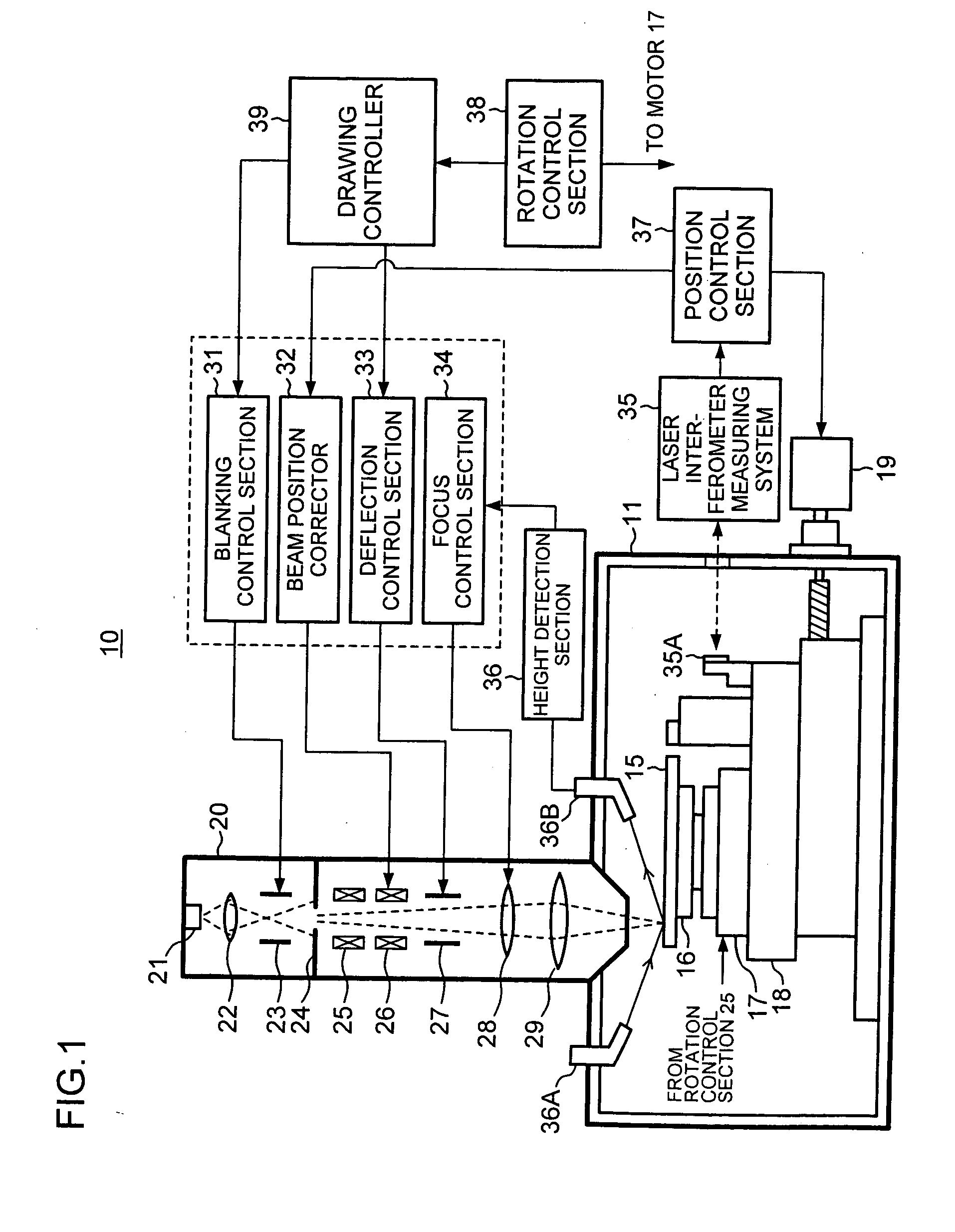
[0023]FIG. 1 is a block diagram schematically showing the structure of an electron beam lithography apparatus 10 according to a first embodiment of the present invention. The electron beam lithography apparatus 10 is a mastering apparatus which produces an original master for manufacturing magnetic disks by use of an electron beam.

[0024] The electron beam lithography apparatus 10 comprises a vacuum chamber 11, a drive device, an electron beam column 20 attached to the vacuum chamber 11, and various circuits and control systems. The drive device performs rotational and translational movement of a substrate mounted thereon and disposed in the vacuum chamber 11. The various circuits and control systems carry out substrate drive control, electron beam control, and the like.

[0025] To be more specific, a substrate 15 for an original master of a disk is mounted on a turntable 16. The turntable 16 is rotated by a spindle motor 17, which is a rotational drive device for driving the substra...

second embodiment

[0045] A second embodiment of the present invention will be hereinafter described with reference to the drawings.

[0046]FIG. 8 is a schematic plan view which illustrates the deflection control when drawing transition is performed from the circle 15A to the circle 15B, and the neighborhood of drawing connection points (start points and end points) is enlarged. FIG. 9 is a time chart corresponding to FIG. 8 which shows the blanking control signal and the deflection control signals in the X and Y directions.

[0047] As in the case of the foregoing first embodiment, the electron beam starts being deflected in a position A near a reference position RA of the circle 15A in the tangential direction (+Y direction in the drawing) opposite to the rotational (moving) direction of the substrate 15, in response to the Y deflection signal having the ramp waveform. In this embodiment, after deflection in the +Y direction starts, deflection velocity is increased from a position B (for example, the r...

third embodiment

[0051] A third embodiment of the present invention will be hereinafter described with reference to drawings.

[0052]FIG. 10 is a schematic plan view which illustrates the deflection control when drawing transition is performed from the circle 15A to the circle 15B, and the vicinity of drawing connection points is enlarged. FIG. 11 is a time chart corresponding to FIG. 10 which shows the blanking control signal and the deflection control signals in the X and Y directions.

[0053] Deflection starts from a position A of the circle 15A in response to the Y deflection signal, and blanking voltage is applied at the predetermined rate of increase from a position B of the circle 15A. In other words, applying the blanking voltage in a ramp form makes it possible to adjust the intensity of the electron beam applied to the substrate. The blanking voltage is rapidly increased in a position C passing a reference position, and the electron beam is completely cut off by blanking (beam: OFF). Namely,...


PUM

PropertyMeasurementUnit
surface recording densityaaaaaaaaaa
recording densityaaaaaaaaaa
shapeaaaaaaaaaa

Abstract

An apparatus includes a beam deflection portion for deflecting the electron beam to change an irradiation position of the electron beam; a synchronization signal generation portion for generating a synchronization signal which is in synchronization with the rotation of the substrate; a controller for controlling the beam deflection portion on the basis of the synchronization signal in order to deflect the electron beam in a rotational radial direction of the substrate and in a rotational tangential direction of the substrate opposite to a rotational direction of the substrate, while drawing transition is performed from one circle to another circle; and a beam cutoff portion for cutting off the irradiation of the electron beam on the substrate, for a period during the electron beam is deflected in the rotational radial direction.

Description

TECHNICAL FIELD [0001] The present invention relates to an electron beam lithography apparatus for manufacturing an original master, and in particular, relates to the electron beam lithography apparatus used for concentrically drawing circles. BACKGROUND ART [0002] A magnetic disk or a hard disk (HD) is used as a storage of a personal computer (PC), a mobile device, a car-mounted device, and the like. The application thereof significantly expands, and surface recording density is rapidly improved in recent years. [0003] To manufacture such a hard disk with high recording density, electron beam mastering technology is widely studied. In an electron beam lithography exposure apparatus, an electron lens converges an electron beam shot by an electron gun, and an electron beam spot is applied to a substrate coated with a resist. A blanking control system and a beam deflection control system control the irradiation position of the electron beam spot to draw a desired beam pattern. Recentl...

Claims


Application Information

Patent Timeline
Patent Type & Authority Applications(United States)
IPC IPC(8): G03C5/00A61N5/00G21G5/00G03F7/20G11B7/135G11B7/26H01J37/147H01J37/305H01J37/317H01L21/027
CPCB82Y10/00B82Y40/00H01J2237/30483G11B7/261H01J37/3174G03F7/2059
Inventor KOJIMA, YOSHIAKI
Owner NUFLARE TECH INC
Why Eureka
Try Eureka