Inverter device

a technology of inverter and upper arm, which is applied in the direction of electronic commutators, process and machine control, instruments, etc., to achieve the effects of improving s/n ratio, preventing noise generated at on/off operations of switching devices in upper arms, and more accurate feedback control

Inactive Publication Date: 2007-07-19
OMRON AUTOMOTIVE ELECTRONICS CO LTD
View PDF4 Cites 30 Cited by
  • Summary
  • Abstract
  • Description
  • Claims
  • Application Information

AI Technical Summary

Benefits of technology

[0016]In the present invention, the sample-and-hold circuit can start sampling later than a time point when the switching device in the upper arm is off, and can stop sampling earlier than a time points when the switching device in the upper arm is on. Accordingly, a noise generated at on / off operations of the switching device in the upper arm can be prevented from being sampled and held, thereby improving an S / N ratio to enable more accurate feedback control.

Problems solved by technology

Therefore, a conventional device detects the phase current based on the voltage across the phase-current detection resistance only when the switching device in the lower arm is on, but does not perform detection of the phase current during the dead time when the switching device in the lower arm is not on.

Method used


Image

  • Inverter device
  • Inverter device
  • Inverter device

Examples


Embodiment Construction

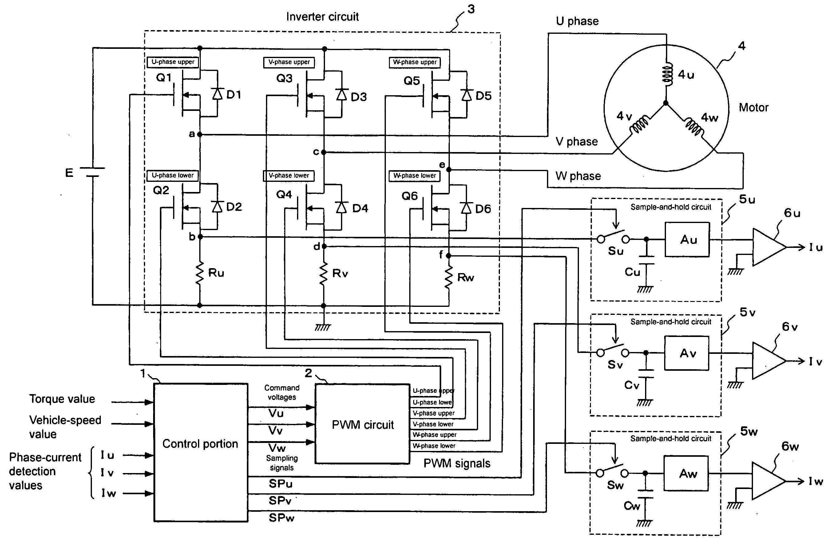
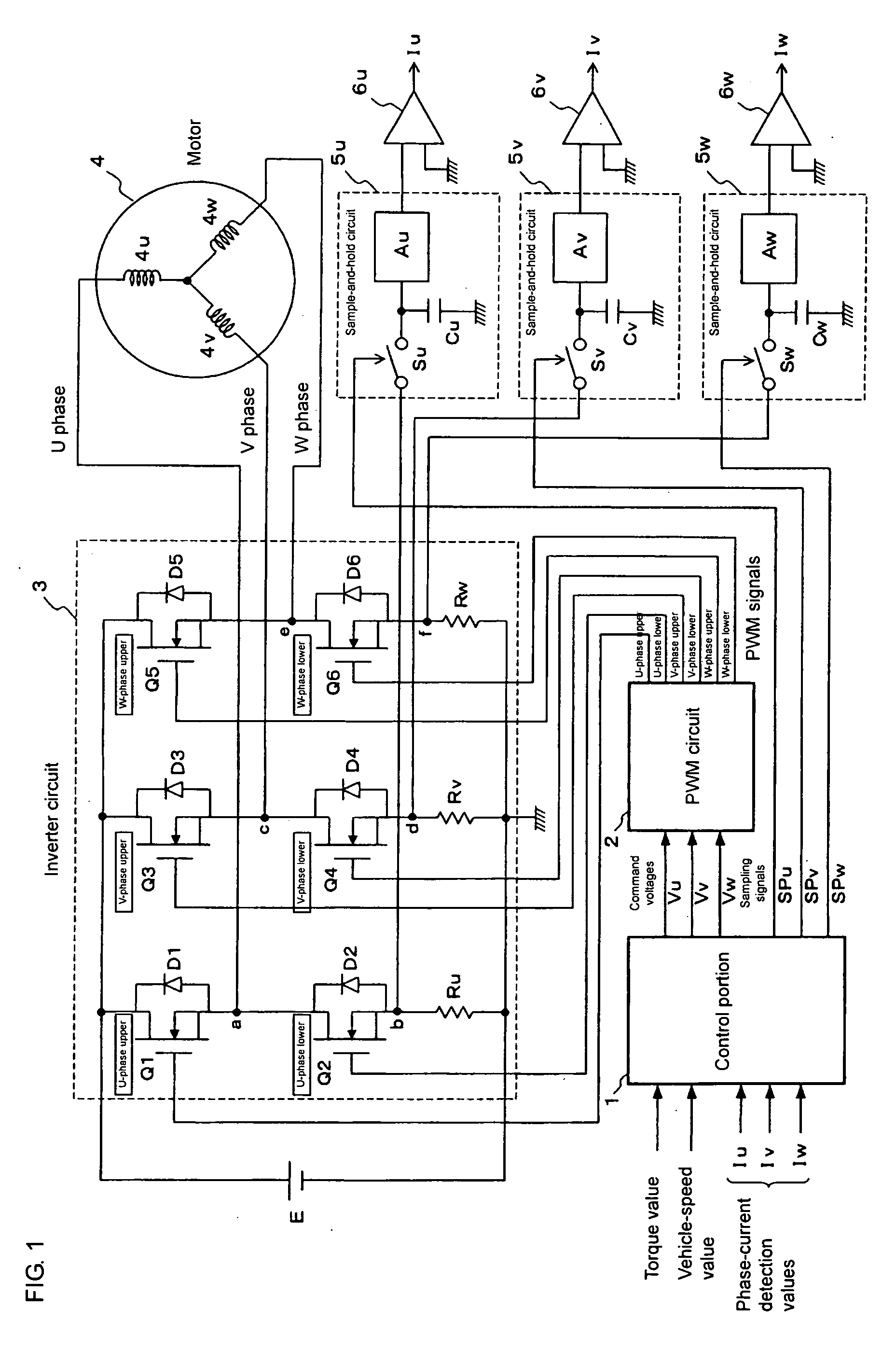
[0029]FIG. 1 is the electrical structure of an inverter device according to an embodiment of the present invention. 1 is a control portion constituted by a CPU, a memory and the like, 2 is a well-known PWM circuit which outputs PWM signals having predetermined duty ratios based on voltage command signals from the control portion 1, 3 is an inverter circuit which outputs motor-driving three-phase voltages (U-phase voltages, V-phase voltages and W-phase voltages) based on PWM signals from the PWM circuit 2, 4 is a motor which is driven by the three-phase voltages output from the inverter circuit 3, 4u, 4v and 4w are the windings of the motor 4, 5u, 5v and 5w are sample-and-hold circuits which sample voltages for detecting the phase currents over a predetermined period and hold the samples, 6u, 6v and 6w are DC amplification circuits which amplify the outputs of the sample-and-hold circuits 5u, 5v and 5w. The PWM circuit 2, the inverter circuit 3 and the sample-and-hold circuits 5u, 5v...


PUM


Abstract

In an inverter circuit including switching devices and diodes connected in parallel with the switching devices which are provided in pairs of upper and lower arms, and also including resistances for detecting phase currents in a motor connected to the lower arms, during dead time periods when both a switching device in an upper arm and a switching device in a lower arm are off, a voltage across a phase-current detection resistance induced by a phase current flowing through a diode is sampled.

Description

BACKGROUND OF THE INVENTION[0001]1. Field of the Invention[0002]The present invention relates to an inverter device for driving a brushless motor used in an electric power steering device in a vehicle, for example, and more particularly, relates to technique for detecting a phase current flowing in a motor.[0003]2. Description of the Related Art[0004]An electric power steering device in a vehicle is provided with a motor such as a 3-phase brushless motor, in order to apply to a steering mechanism a steering aiding force corresponding to a steering torque of a handle. The steering torque applied to the handle is detected by a torque sensor and, according to a detected value thereof, a target value of an electric current to be flowed through the motor is calculated. Then, based on a difference between the target value and the value of the electric current actually flowing through the motor, a command value for feedback control to be supplied to a motor driving portion is calculated. A...

Claims


Application Information

Patent Timeline
Patent Type & Authority Applications(United States)
IPC IPC(8): H02M3/24H02M7/48H02P6/06H02P6/08H02P6/16H02P6/28
CPCH02M7/53873H02P27/08H02M2001/0009H02M1/0009G01R19/14H02P7/29
Inventor GUNJI, KEITA
Owner OMRON AUTOMOTIVE ELECTRONICS CO LTD
Why Eureka
Try Eureka