Cell module for fuel cell, method for forming cell module, and fuel cell

a fuel cell and cell module technology, applied in the field of fuel cell cell modules, can solve the problems of increasing limit, inability to form cells that are drastically thinner than the commonly used cells, and difficulty in meeting the demand for more compact fuel cells, etc., to achieve the effect of reducing internal resistance of the cell module, increasing electric power generation efficiency, and high electric power generation efficiency

Inactive Publication Date: 2007-07-19
TOYOTA JIDOSHA KK +1
View PDF1 Cites 48 Cited by
  • Summary
  • Abstract
  • Description
  • Claims
  • Application Information

AI Technical Summary

Benefits of technology

[0023]With such structure, the nano-columnar bodies, which support the electrode catalytic metal particles and which are oriented toward the hollow-core electrolyte membrane, are formed on the collecting member. The area on and around the collecting member, where there are nano-columnar bodies, more specifically, the portion in the area, where there are the nano-columnar bodies oriented toward the hollow-core electrolyte membrane is used as the electrode in which the electrode catalytic metal particles are densely supported on the nano-columnar bodies. In fuel cells, the electrode reaction occurs at a portion, at which an electrode catalyst contacts a proton-conducting substance and to which the reaction gas is supplied, namely, a three-phase interface. In the above-described structure, the electrode is formed by aligning the nano-columnar bodies, on which the electrode catalytic metal particles are supported, so that the nano-columnar bodies are oriented toward the hollow-core electrolyte membrane. Accordingly, the reaction gas supplied for the electric power generation easily comes close to the three-phase interface, and is uniformly dispersed. As a result, the electrode catalytic metal particles supported on the nano-columnar bodies are effectively used for the electrode reaction.
[0026]In the structure formed in the above-described manner, the area(s) on and around the first collecting member or / and the second collecting member, in which there are the nano-columnar bodies, serve(s) as the electrode formed integrally with the collecting member. At the electrode including the nano-columnar bodies, the reaction gas efficiently reaches the electrode catalytic metal particles densely supported on the nano-columnar bodies, and the three-phase interface near the electrode catalytic metal particles. Accordingly, the electrode catalytic metal particles supported on the nano-columnar bodies effectively contribute to the electrode reaction, which increases the electric power generation efficiency.
[0027]In the cell module according to the aspects of the invention, the nano-columnar bodies, which support the catalysts, are connected, at one ends, to the collecting member, and the other ends of the nano-columnar bodies are oriented toward the hollow-core electrolyte membrane. Accordingly, the electric charges are smoothly exchanged between the electrode and the collecting member / the hollow-core electrolyte membrane. Accordingly, even in a cell module that includes a hollow-core electrolyte membrane with which it is difficult to apply an external surface pressure, appropriate electric connection between the electrode and the collecting member is maintained, and the internal resistance of the cell module is reduced. Therefore, the cell module exhibits high electric power generation efficiency, and the fuel cell formed by gathering such cell modules together has excellent electric power generation efficiency.

Problems solved by technology

Even if thinner electrolyte membranes are used to further increase the power density, it is not possible to form cells that are drastically thinner than the commonly used cells.
However, there is a limit to increases, due to reduction in the thickness of such members, in the power density per unit volume.
For such reason, it may be difficult to meet the demand for more compact fuel cells.
In addition, there is a disadvantage that the production cost of fuel cells is high.
However, the carbon materials are expensive.
Microfabricating such grooves makes the separators considerably expensive.
This drastically increases the production cost of the fuel cells.
For example, it is technically difficult to reliably provide sealing to the periphery of each of the multiple cells stacked on top of each other in order to prevent the fuel gas and the oxidant gas from leaking from the gas passages.
Further, the electric power generation efficiency may be reduced due to deflection or deformation of the flat membrane-electrode-assemblies.
However, under the present circumstances, it is difficult to appropriately design the three-phase interface.
Due to such inconveniences, the expensive catalysts made of noble metal are not effectively used.
As described above, it is difficult to perform design so that the three-phase interface is controlled to effectively use the electrode catalysts.
In the hollow-core cell modules, it is also difficult to perform design so that the three-phase interface is controlled to effectively use the electrode catalysts.
Unlike the flat cell modules, in the hollow-core cell modules, it is difficult, due to the shape and the structure, to apply surface pressure for causing the electrodes and the collecting members to contact more closely.
Accordingly, the conduction of electricity is likely to be insufficient.
Accordingly, the conduction of electricity is more likely to be insufficient due to insufficient surface pressure.

Method used


Image

  • Cell module for fuel cell, method for forming cell module, and fuel cell
  • Cell module for fuel cell, method for forming cell module, and fuel cell
  • Cell module for fuel cell, method for forming cell module, and fuel cell

Examples


first embodiment

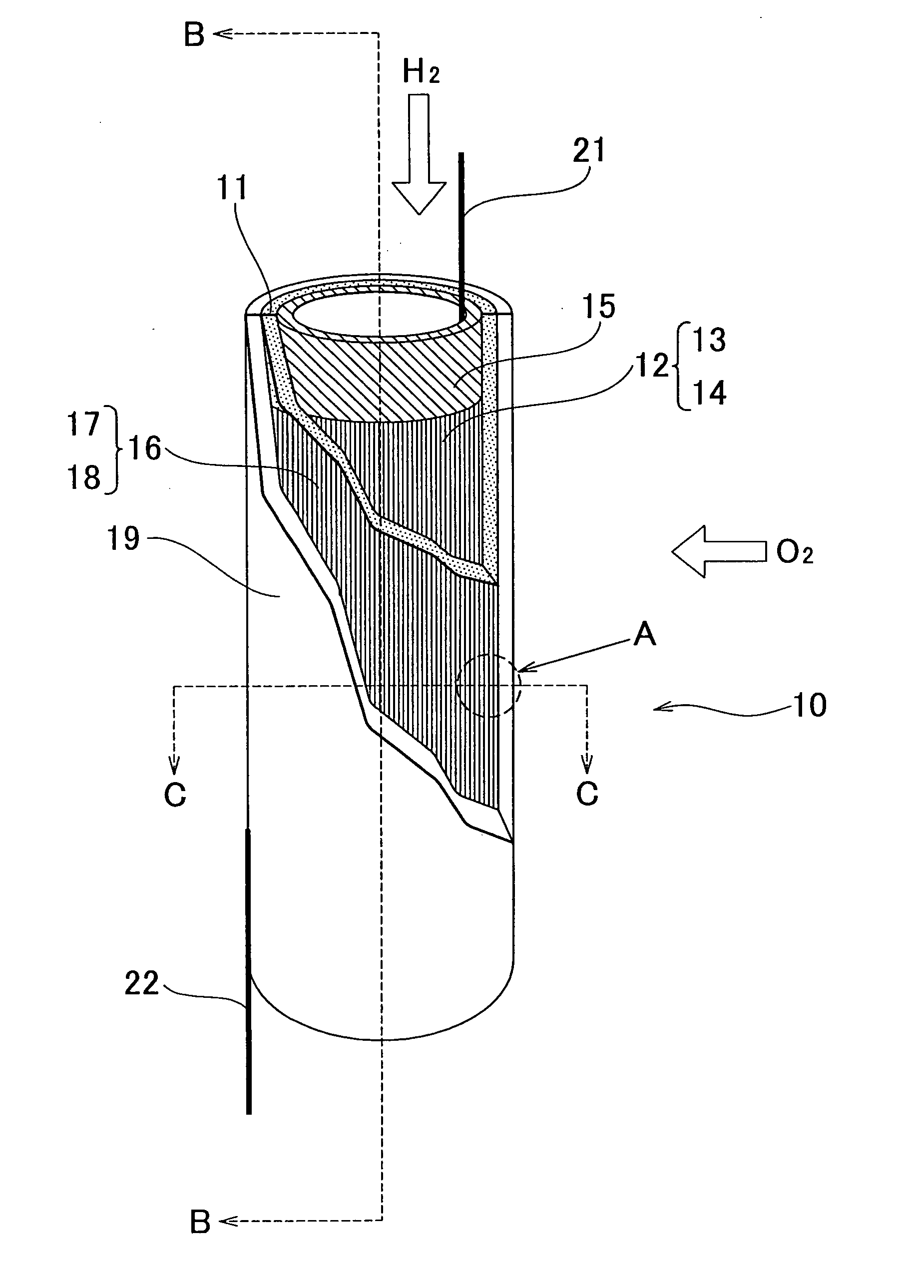
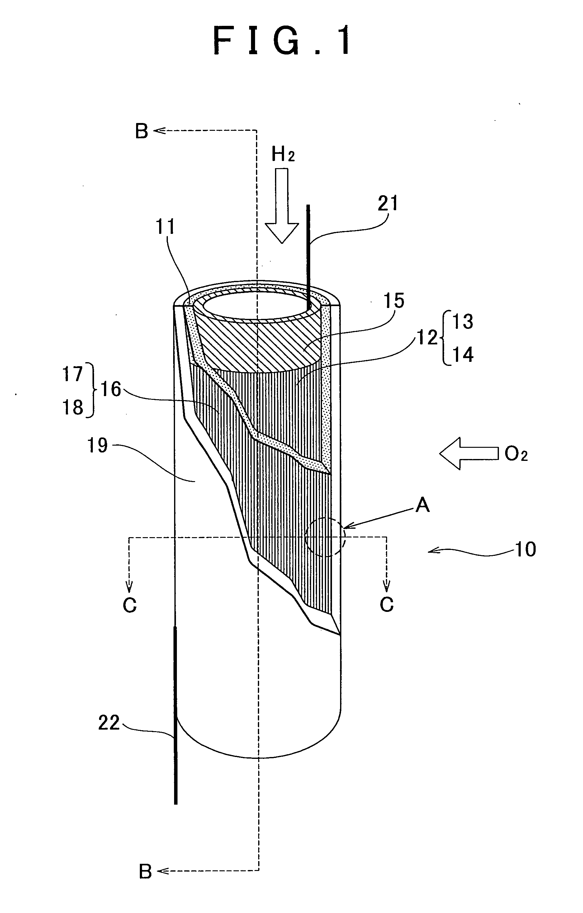
[0040]The hollow-core electrolyte membrane (the fluorine ion-exchange resin membrane 11, in the first embodiment) is a hollow-core member that is open at both ends. Accordingly, separators are not required, and a large electrode area, which is used for electric power generation, is obtained.

[0041]Although not limited to certain values, the outer diameter of the hollow-core electrolyte membrane 11 is preferably 0.01 mm to 10 mm, more preferably 0.1 mm to 1 mm, and optimally 0.1 mm to 0.5 mm. Under the present circumstances, it is technically difficult to form the hollow-core electrolyte membrane 11 having an outer diameter of less than 0.01 mm. However, if the outer diameter of the hollow-core electrolyte membrane 11 exceeds 10 mm, the surface area with respect to the occupied volume is not sufficient. Accordingly, the effects of increasing the power output per unit volume of the cell module may not be sufficiently produced.

[0042]Preferably, the fluorine ion-exchange resin membrane 1...

second embodiment

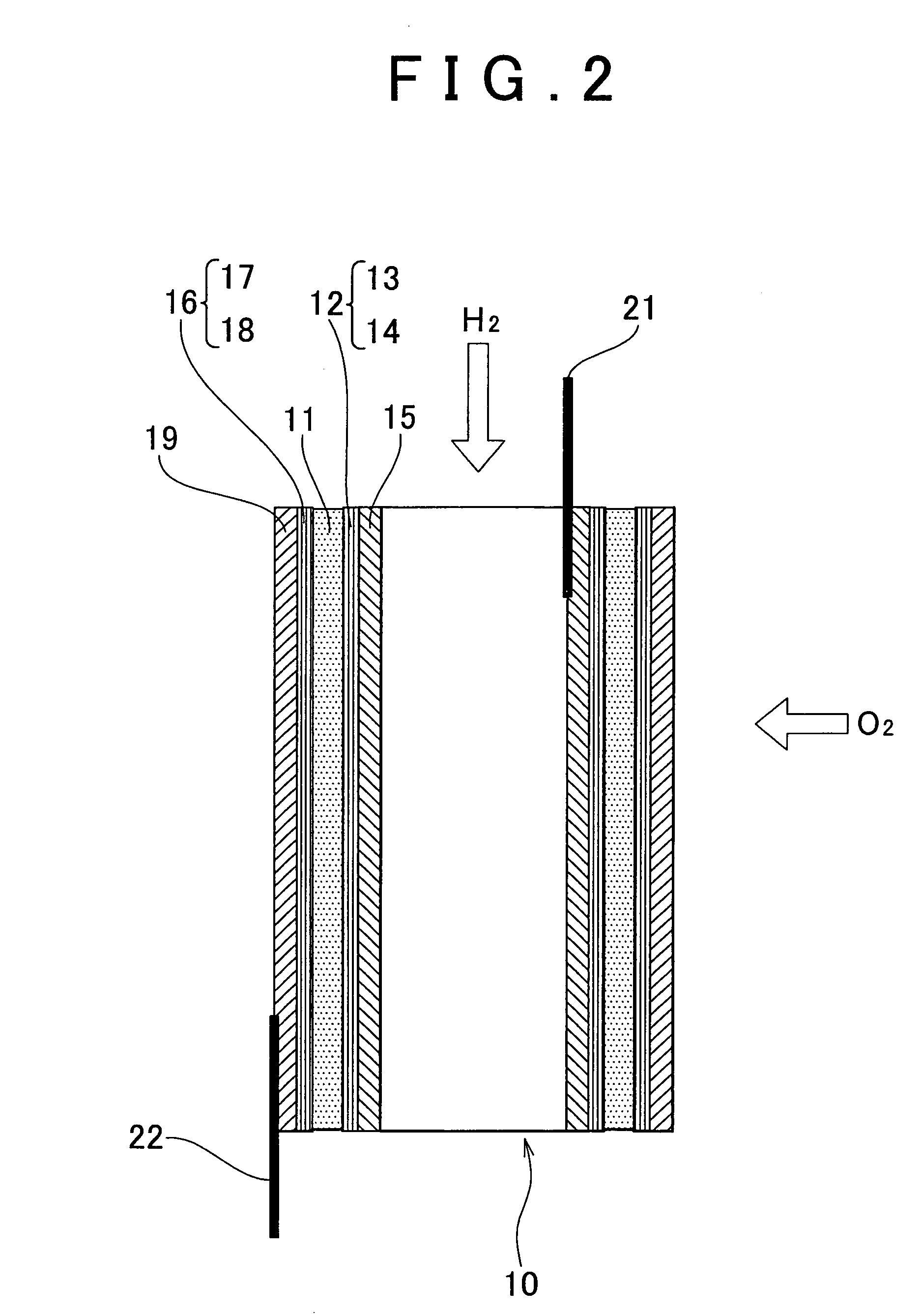
[0118]Next, the method for forming the cell module 70 according to the invention will be described below.

[0119]The first carbon fiber layer 72 is formed on the first SUS pipe 15, which is the hollow-core conductor, to form the first intermediary body, for example, in the first CNT fixation collecting member coating step. In the first CNT fixation collecting member coating step, first, the short carbon fibers on which the carbon nanotubes are formed are dispersed in the solution, and the composition for forming of the CNT fixing carbon fiber layer is formed by adding an additive selected from various additives to the solution when required, and the outer face of the first SUS pipe 15 prepared in advance is coated with the CNT fixing carbon fiber layer forming composition. Although the liquid used as the solution is not limited to a certain liquid, for example, acetone is preferably used. Examples of preferable additives include a conductive filler that is the component used in a cond...


PUM

PropertyMeasurementUnit
lengthaaaaaaaaaa
thicknessaaaaaaaaaa
thicknessaaaaaaaaaa

Abstract

A cell module for a fuel cell according to embodiments of the invention includes a hollow-core electrolyte membrane; two electrodes one of which is arranged on the inner face of the hollow-core electrolyte membrane and the other of which is arranged on the outer face of the hollow-core electrolyte membrane; and first collecting members that are connected to the respective two electrodes. At least one of the two electrodes includes nano-columnar bodies on which electrode catalysts are supported. The nano-columnar bodies are formed on at least one of the first collecting members corresponding to the at least one of the electrodes that includes the nano-columnar bodies. At least part of the nano-columnar bodies are oriented toward the hollow-core electrolyte membrane.

Description

BACKGROUND OF THE INVENTION[0001]1. Field of the Invention[0002]The invention relates generally to a cell module suitable as an electric power generation portion of a fuel cell, and, more specifically, to a cell module including a hollow-core electrolyte membrane. The invention also relates to a method for forming such cell module, and a fuel cell in which such cell module is used as a cell.[0003]2. Description of the Related Art[0004]In fuel cells, fuel and an oxidant are supplied to two respective electrodes electrically connected to each other, and the fuel is electrochemically oxidized, whereby chemical energy is directly converted into electric energy. Unlike thermal electric power generation, electric power generation by the fuel cells is not restricted by the Carnot cycle. Accordingly, the fuel cells exhibit high energy conversion efficiency. In polymer electrolyte fuel cells, polymer electrolyte membranes are used as electrolytes. Attention has been given to the polymer elec...

Claims


Application Information

Patent Timeline
Patent Type & Authority Applications(United States)
IPC IPC(8): H01M4/86H01M8/10H01M4/92H01M8/02
CPCB82Y30/00H01M4/86Y02E60/521H01M8/0254H01M8/1004H01M4/92Y10S977/948Y02P70/50Y02E60/50
Inventor NAKANISHI, HARUYUKIMURATA, SHIGEAKIHOSHINO, MASAHITOHAYASHI, HIROAKIKOZUKA, KIYOMI
Owner TOYOTA JIDOSHA KK
Why Eureka
Try Eureka