Task-based robot control system for multi-tasking

a robot control and multi-tasking technology, applied in the field of pc-based robot control system, can solve the problems of complex hardware construction, inconvenient modern production line structure, user may feel difficult in constructing tasks, etc., and achieve the effect of improving productivity, reducing complexity in the existing robot system design process, and increasing the degree of understanding of tasks by users

Inactive Publication Date: 2007-07-19
ROBOSTAR
View PDF9 Cites 59 Cited by
  • Summary
  • Abstract
  • Description
  • Claims
  • Application Information

AI Technical Summary

Benefits of technology

[0022] In addition, in the task-based control system, since each task operates independently, it does not affect other tasks although an exceptional situation happens during the task. If this method is applied to a business robot control machine, the complexity occurring in the existing robot system design process can be reduced and the degree of understanding on the task by a user can be increased. It is thus possible to improve the productivity and save the cost for constructing development environment.
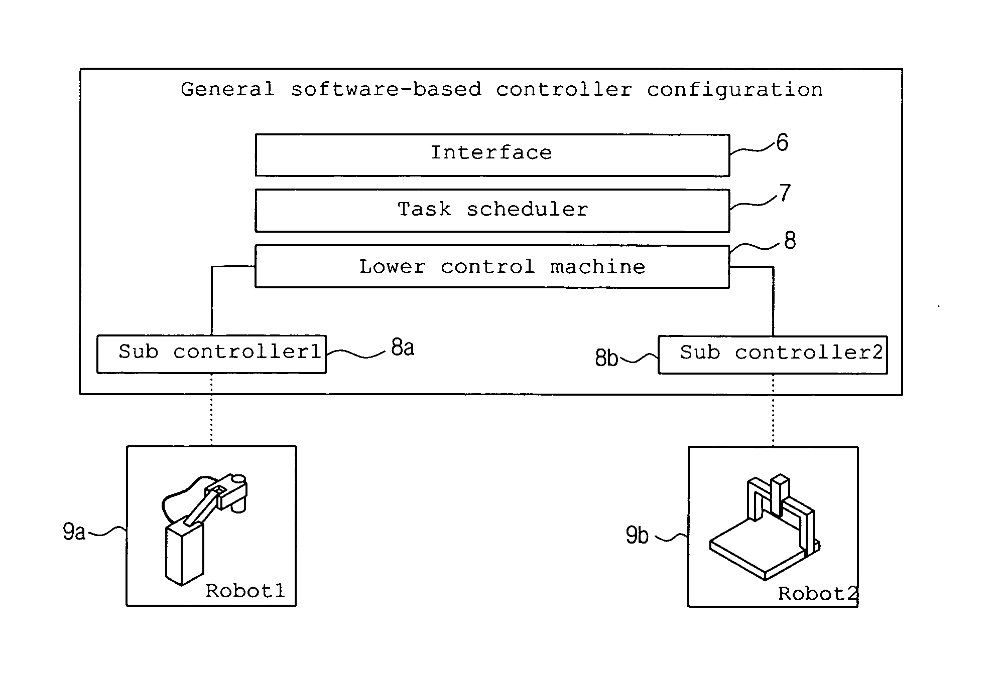
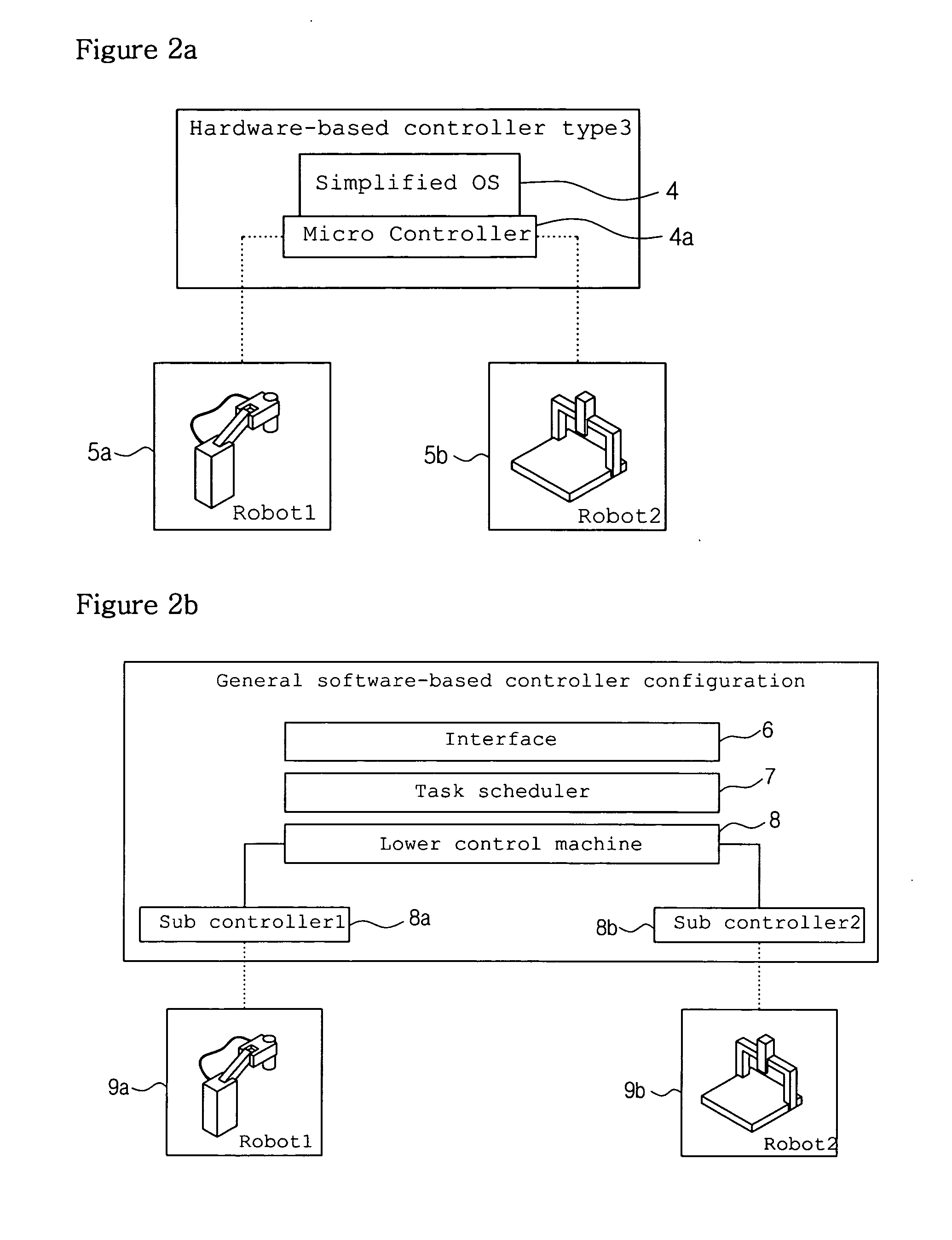
[0023] In accordance with the present invention, an existing hardware-based robot control machine type can be applied as a new software-based robot control machine and software-based multi-tasking is enabled. Accordingly, a user can construct work environment efficiently in comparison with an exist

Problems solved by technology

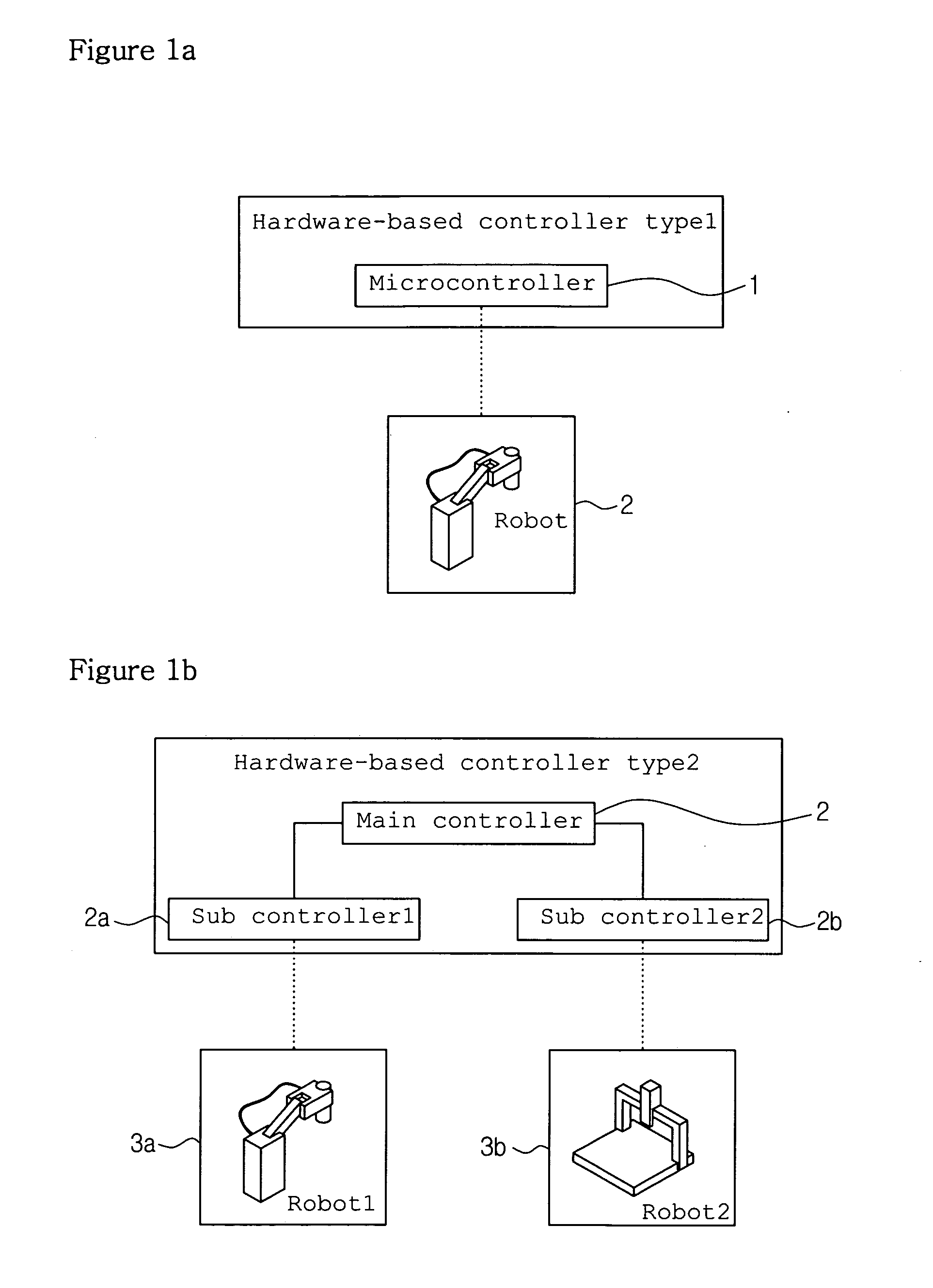
It was found that such configuration is not suitable for a modern production line structure having a multi-kind and small-quantity production scheme.
Therefore, the construction can perform multi-tasking in terms of function, but is disadvantageous in that the construction of hardware becomes complicated as a ta

Method used


Image

  • Task-based robot control system for multi-tasking
  • Task-based robot control system for multi-tasking
  • Task-based robot control system for multi-tasking

Examples


Embodiment Construction

[0041] The present invention will now be described in detail in connection with embodiments with reference to the accompanying drawings.

[0042]FIG. 3 is a conceptual view of a task-based robot control machine according to an embodiment of the present invention.

[0043] A plurality of virtual controllers 1-N are arranged in parallel in a task-based software controller 100.

[0044] The virtual controllers 1-N are constructed to control corresponding robots 1 to N, respectively. The controller 100 refers to a robot control system including a software-based virtual robot control machine to be described later.

[0045] As shown in FIG. 3, the controller of the present invention has a horizontal and parallel structure not a vertical structure.

[0046]FIG. 4 is a block diagram showing the construction of a robot control system according to an embodiment of the present invention.

[0047] The robot control system includes:

[0048] an external apparatus 10 including a High Level Robot Program Langua...


PUM


Abstract

The present invention relates to a PC-based robot control system, which is a new type of a robot control machine. The present invention has aimed at a task-based control machine configuration not a centralized control configuration so that a multi-tasking function is possible through a distributed control system. An embodiment of the present invention provides a task-based robot control system, including robot system interface means that receives a control command for controlling a robot; system kernel means that controls the creation and distinction of one or more software-based virtual robot control machines of virtual robot controller means, which will be described later, in a software way and controls the synchronization between the virtual robot control machines, based on the control command received from the robot system interface means; the virtual robot controller means having one or more software-based virtual robot control machines whose creation and distinction are controlled under the control of the system kernel means, wherein a generated virtual robot control machine processes a robot control execution sentence input through the robot system interface means; and hardware means that actually drives the robot according to a control signal generated by the processing of the execution sentence by the virtual robot control machine.

Description

BACKGROUND OF THE INVENTION [0001] 1. Field of the Invention [0002] The present invention relates to a system of a PC-based robot control machine. More particularly, the present invention relates to a task-based robot control system for multi-tasking, in which an existing hardware-based robot control machine type can be applied as a new software-based robot control machine and software-based multi-tasking is enabled, whereby it is significantly advantageous for a user to construct work environment as compared with an existing PC-based control machine, and the productivity can be improved and the production line design cost can be saved through the improvements of user convenience. [0003] 2. Background of the Related Art [0004] A PC-based control machine refers to a software-based control machine in which a hardware or firmware-based control machine implemented by existing DSP or ASIC is programmed using software so that it can be used in a PC. A main reason why the application of a ...

Claims


Application Information

Patent Timeline
IPC IPC(8): G06F19/00
CPCB25J9/1658G05B2219/34403G06F9/485G06F9/3851G05B2219/40519A47J37/0694A47J37/0786
Inventor KIM, BONGJOONOH, JUNGMINPARK, POOGYEON
Owner ROBOSTAR
Why Eureka
Try Eureka